 |
October 8, 2005:
(0.5 hrs.) It has been hard finding time to work on the
plane lately. Work and related travel have kept me very busy.
I did manage to get out to the garage for 30 minutes and begin work on
the aileron control rods. I would like to get these completed
prior to mounting the ailerons and flaps.
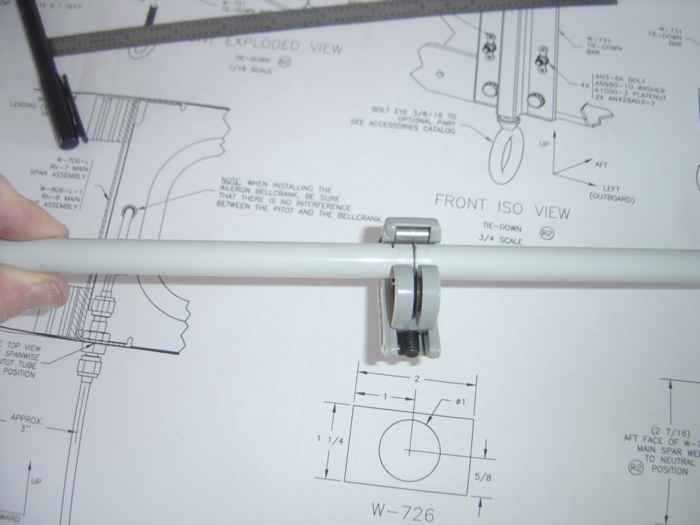
Here I am using a tubing cutter to cut-to-length
the bell crank to aileron control rods. Using a tubing cutter gave
a nice straight cut compared to the bandsaw. |
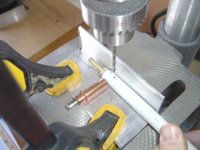 |
Here I am using my drill press to drill
the #30 holes for the rivets that will hold on the end-rod in place.
Pretty easy work.
I also managed to cut the tubing to length for the aileron bell-crank
to fuselage control rods. Well that's all for today. I a
have quite of bit of over seas travel coming up so it may be a while
before I get back to work on this stuff. |
 |
November 5, 2005:
(2 hrs.) Back at it again after 4 weeks of business travel.
Today I prepped and primed the inside of the control rods. Once
that was dry, I installed the rod ends. For the bell-crank to
fuselage aileron control rod, the ends get blind riveted in six places.
I made sure to dip each blind rivet in primer as I set them. For
the aileron to bell-crank control rods, the ends get solid rivets.
I found the best way to set these was to use my C-Frame.
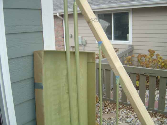
Lastly, I cleaned the external surfaces of the
control rods and primed them. Here are they are hanging out to
dry. |
 |
November 12, 2005:
(2.0 hrs.) Dan was nice enough to stop by today to help out
on the plane. I needed an extra set of hands to complete the
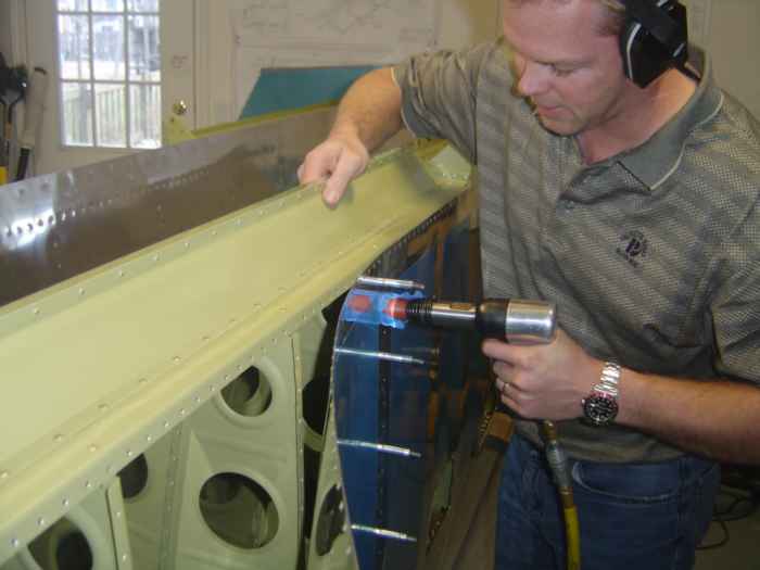
closing of the left wing, so that was the project of the day.
Here is Dan shooting while I manipulated the
bucking bar. |
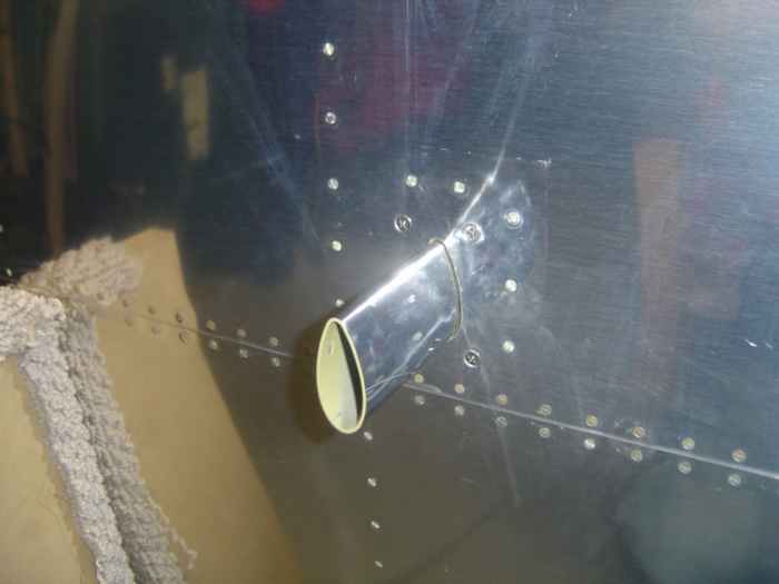 |
When closing the left wing, I had to
remember to set the rivets for the pitot tube mounting plate. This
is a picture of the mounting plate riveted in place and the pitot tube
extension mount screwed to the pate. |
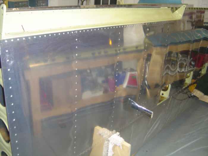 |
Left wing closed! |
 |
November 19-20, 2005:
(2.0 hrs.) Installed the left and right ailerons.
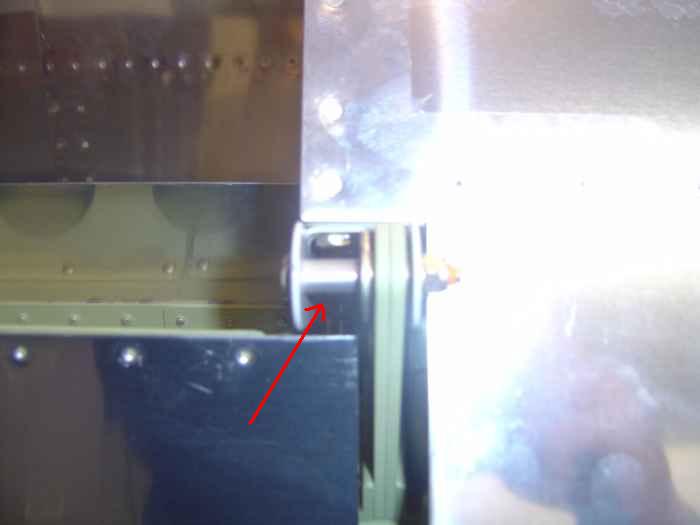
Several bushing need to be created out of supplied aluminum tubing that
will act as spacers where the aileron attaches to the hinge brackets.
Here is a shot of one such spacer (pointed to by red arrow). |
 |
Assembled the aileron
bell cranks. This entails drilling out the brass bushing to accept
the AN bolt. I did this by holding the bushing in my bench mounted
vice and drilling out the center hole using my hand drill and lots of
Boelube. This hole does not need to be perfect because the bushing
does NOT rotate around the AN bolt, but rather the bell-crank rotates
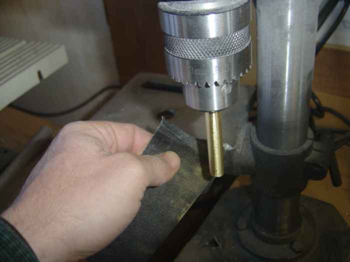
around the bushing. The first bushing did
not fit very good in the bell-crank. I chucked the bushing the up
in the drill press and and sanded it smooth. This helped with the
fit.
|
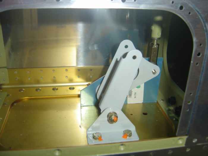 |
Here the left aileron bell-crank is
installed in the wing. The aileron 'neutral-position' adjustment
plate (blue) is temporarily holding the bell-crank and push tube in
position. The idea here is that the adjustment plate will hole the
bell-crank in position, and you adjust the push rod length so that the
aileron sits vertical and inline with the wing rib tooling holes (see
below). |
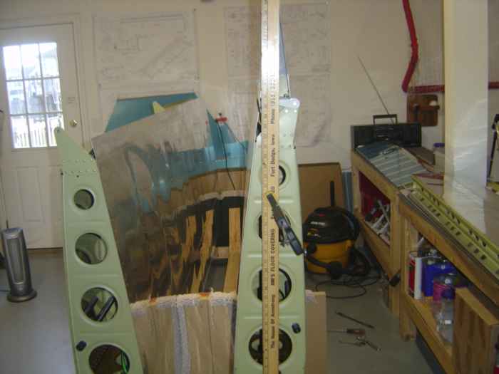 |
Here I have clamped a yard stick along the
Van's indicated tooling holes that will determine the correct aileron
trailing edge neutral position. |
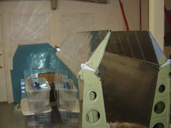 |
Both ailerons attached. |