 |
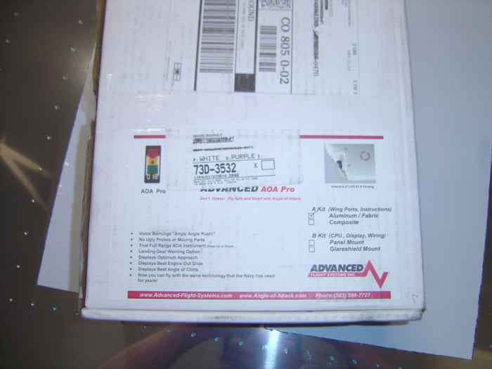
April 21, 2005: (1.0 hrs.) I received my Advanced Flight Systems angle of attack (AOA) 'a' option kit today. The 'a' option kit is everything that is needed to mount the system in your wing. Later on, when I am adding in the avionics to my plane, I will purchase the 'b' option kit which is the computer and display for this unit. I will be installing the pressure port sensors in my right wing (currently jigged), so I should have details on the installation soon. |
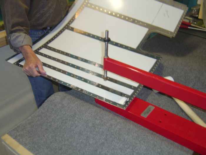 |
Worked with Max to finish dimpling the right wing bottom skins. That's it, dimpling is now complete on the right side! |
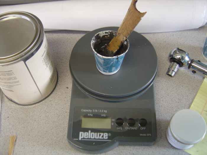 |
May 1, 2005: (1.0 hrs.) Decided to take a break from the tanks for a while and install the pressure ports for the angle of attack system. Here I mixing up ProSeal in a small dixie cup. I use a postal scale to measure out the 10:1 proportions of compound prior to mixing. |
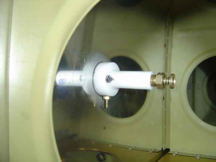 |
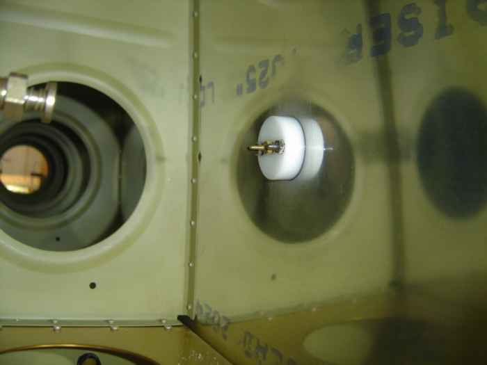
I installed the pressure ports in the
right outboard wing bay. Both the top and bottom pressure ports
are installed 6" forward from where the leading edge skin intersects the
main spar. The top port is 4 3/4" in from the leading edge
outboard skin edge. The bottom port is 7 1/2" in from the leading
edge outboard skin edge. The installation manual from Advanced
Flight Systems is very specific on the placement of these ports. The pressure ports get attached with flush head screws (come with the kit) or rivets. The rivets must be installed on the inboard and outboard side of the port (not in the front and aft of the port, this could interfere with the airflow over the port). Here the top port has been attached with flush head screws and ProSeal. Notice this port has a drain valve. This is to remove any water that may accumulate in the port. Strange thing is, the system does not come with any hardware to extend this drain down to the bottom skin so that is can be easily accessed and water can drain out of the wing. The manufacturer recommends just drilling a #40 hole in the bottom of the wing and using a long wire rod (comes with kit) to activate the drain. I don't like the idea of fishing around to find this drain every time I want to activate it. Nor do I want water to just drain into my wing. I will try to extend this drain. |
 |
Here is the bottom port installed. There is no drain valve on this port. |
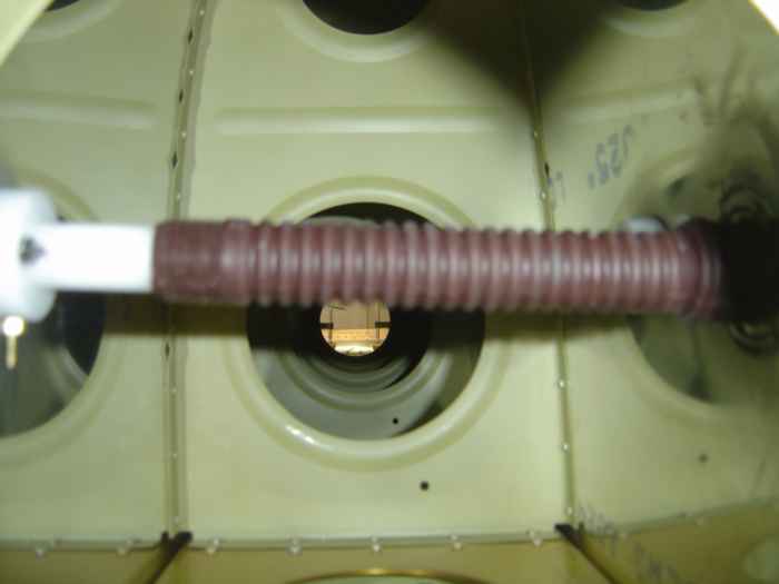 |
This is my solution to the top port water drain. I added this tubing that extends the port down to the bottom skin where I ProSealed the tube in position. I then drilled a #40 hole in the bottom skin where the extension tube is attached. I can now use the tube as a guide for the drain actuator rod. The tube will also allow water to drain out of the wing. If your wondering what kind of tube I used, it is a 1/2" flexible sprinkler riser with a male connection at one end, and a female connection at the other. I picked this up and Home Depot. It is light, durable, and fit the port perfectly. The male end slides snuggly over the port. I cut the female end at a slight angle so it would sit flush with the bottom skin. I then put a bunch of ProSeal around the bottom end to make sure it does not slide out of place. The whole setup seemed to be nice and snug. Just as an added precaution and I drilled and screwed the extension tube to the top pressure port (this is not shown in the picture). |
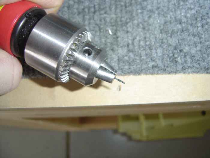 |
The skin needs to be drilled with a #60
drill right over the top and bottom ports. This will allow the
pressure from the surface airflow to be picked up by the ports and
register with the AOA onboard computer. The kit comes with required
drill bit. It is tiny!
Notice I slid nearly the entire bit up in the chuck. This helps keep it from snapping when you are drilling the holes. |
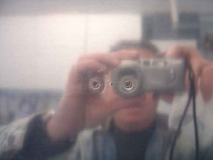 |
Here is a nice artsy shot of the upper pressure port from the outside of the skin. You can see the two flush head screws and the small #60 hole in between them. |
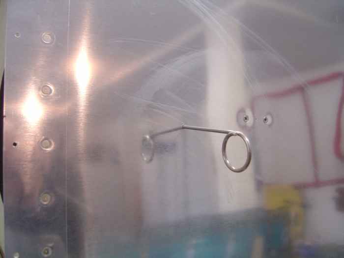 |
This is a shot of the bottom skin. Kind of hard to see, but to the right is the bottom pressure port (you can see the two flush head screws). The center of the picture is the water drain actuator rod inserted in the wing just for the picture. You don't fly with this rod in place! It is only used during the pre-flight to clear any water out of the system. |