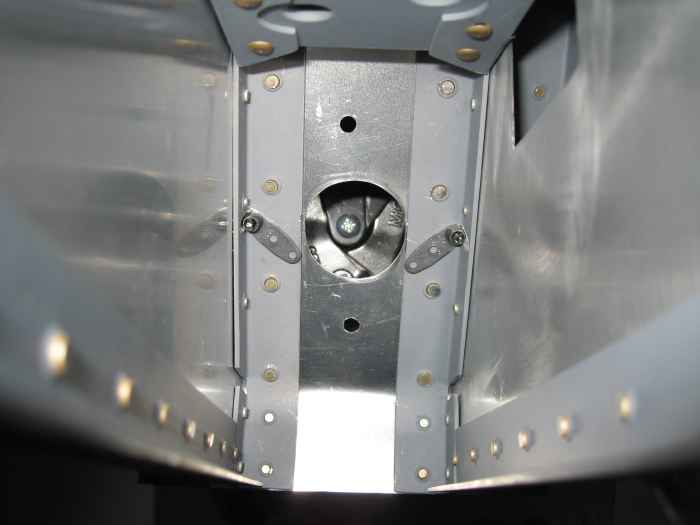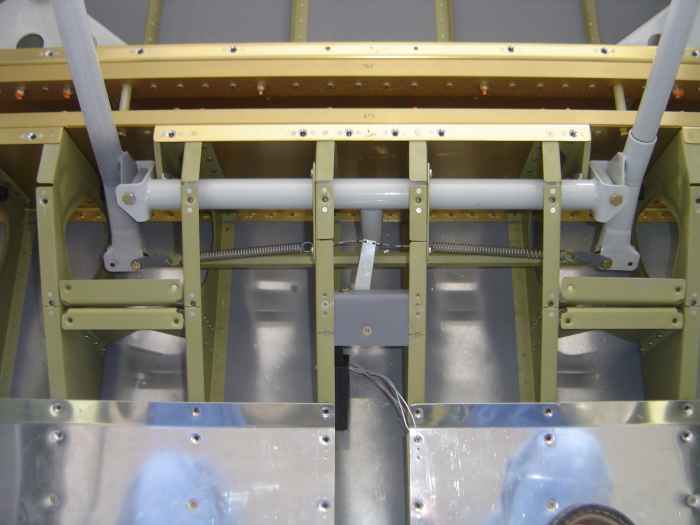
Sorry, but I did not take the normal number of pictures during this build session. I spent the majority of my time finishing up the aileron electronic trim system.
This picture shows the final assembly of the trim server (attached to the seat bottom rib), the trim arm and mounting bracket (attached between the two center seat bottom ribs), and the spring biased tension system (attached from the trim arm to both control sticks. I tested the system by hooking up my cordless drill battery to the trim servo, and running the servo in both directions. It works very nicely.
Installation was fairly simple with no real gotcha's. I did have to use a right angle drill attachment to match drill the trim servo to the seat bottom rib.
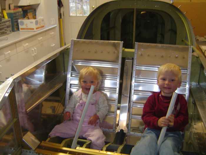
Here are the seat backs installed and being tested by my test pilots. They seem to like the fit!
Looking at my list of items that still need to be completed, I have: fabricate and install center console, complete fuel lines and AP fuel pump install, install vent lines, install brake pedals, install brake lines, remove everything and paint interior, ..... the list goes on.
BTW, my finish kit is supposed to ship today.
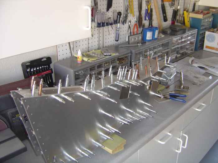
Finish kit arrived on Friday afternoon and I took time to crack the crate open. Once I had everything inventoried and put away, I could concentrate on some more fuselage work.
Began building the center console. This is a design and kit by another RV builder, Bryan Fillman. This takes up a little extra space and adds some weight, but should prove useful as an armrest and for mounting the throttle quadrant.
Here I am match drilling and cleco'ing the assembly together.
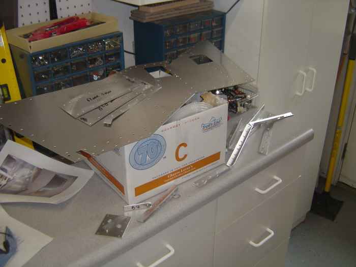
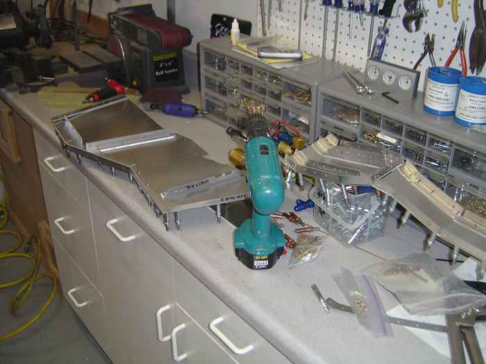
I have only been able to work on the project in short shifts over the course of the last few weeks. Working in this manner, I have somehow managed to not take as many pictures.
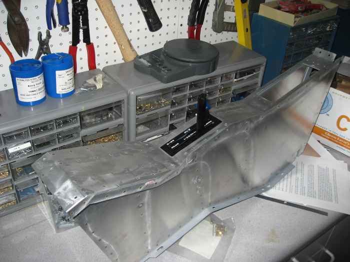
After completing all the deburring and dimpling of the center section, I primed the interior skeleton. Next the entire assembly was riveted together over several sessions. Most rivets could be hand squeezed, a few were shot with the pneumatic gun, and a few blind rivets were used in tight areas. After the console was assembled, I measured (like 5 times) and made the cut-out for the throttle quadrant. This is a quadrant that Dayton Murdock at DJM Mfg made at my request. I wanted a two lever quadrant for a FADEC setup (Throttle and Prop RPM). The picture shows the quadrant in position with the T handle for the throttle removed.
.
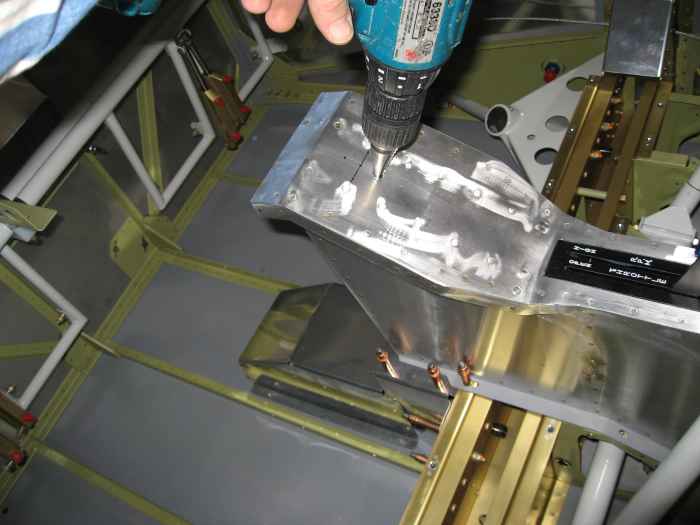
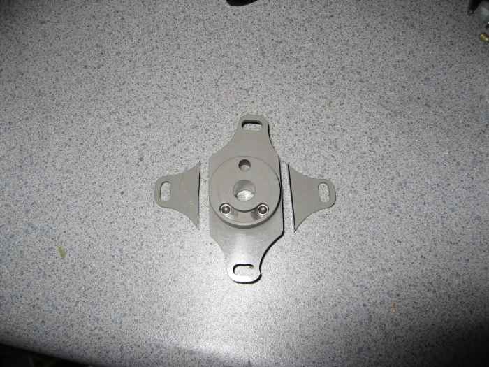
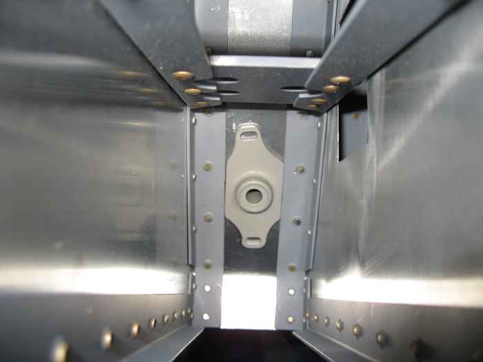
The fuel selector valve face plate had provisions for 4 screws, so I still had to drill the holes for the side screws through the console. These holes came awful close to the side facing web of the aluminum angle as you will see in a follow on picture. The problem was determining how I would secure the screws. There was no room for a standard nut-plate, and definitely not enough room for a washer and nut.
