 |
November
10-12, 2006:
(8.0 hrs.) There were a few things I needed to
complete on the center console before I could declare it finished.
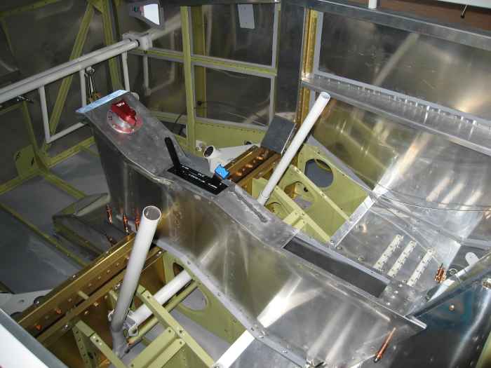
Here is a shot of the console from rear. The forward top of the
console will attach to the panel. The hole in the top aft section
of the console will have a hinged lid and act as glove box. The
plan is to upholster the console using the same leather as will be used
for the seats. It should look really sharp. |
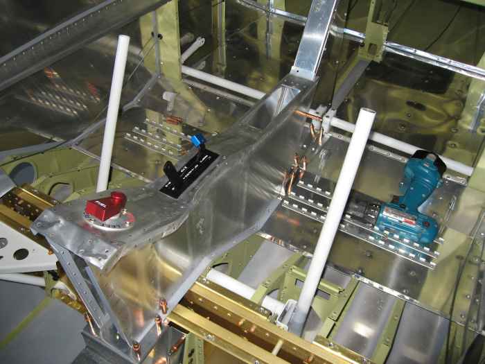 |
Here is picture from the from of the
console. After I took this shot, I took the console out and
removed the throttle quadrant. I needed to adjust the quadrants
friction lock, and short then screws that attach the quadrant to the
console. |
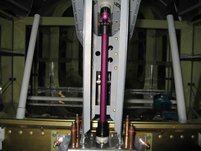 |
Another item I had to address on the
console, was the fuel valve extension mechanism. Here you can see
I have installed the fuel valve extension coupler (bottom), union joint
(top), and extension rod. The rod had to be cut to the proper
length. |
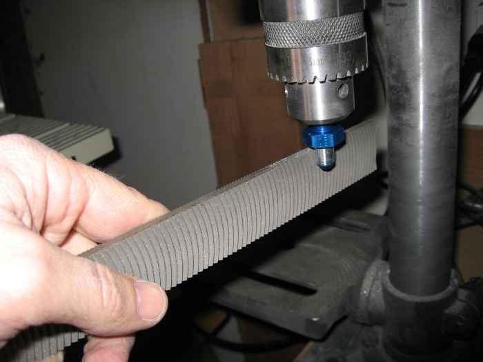 |
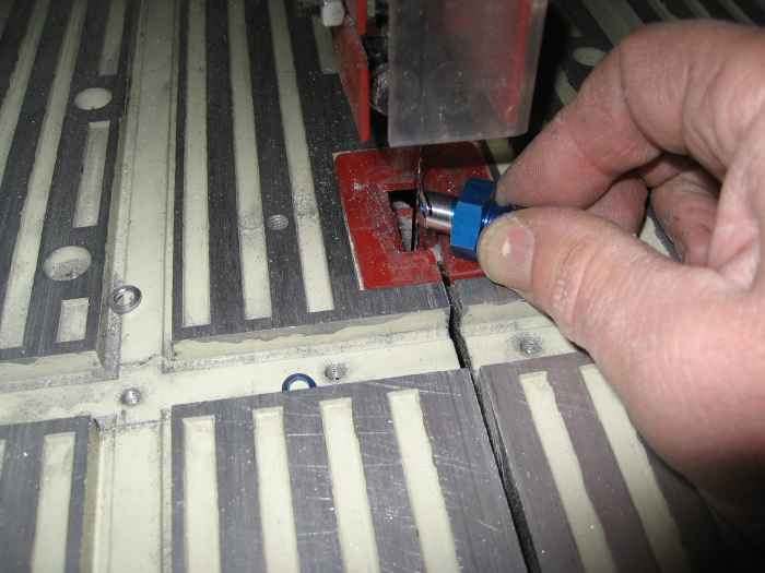
With the console completed, I moved on to
the fuel vent lines. The first thing I did was work on the
bulkhead fitting for where the vent line exits the fuselage. I
chucked the AN straight 1/4" fitting into my drill press and then ran a
file along the thread to remove them. I followed that by running
some fine sand paper along the newly formed nipple to smooth things out.
You have to make two of these. One each for the left side and
right side vents |
 |
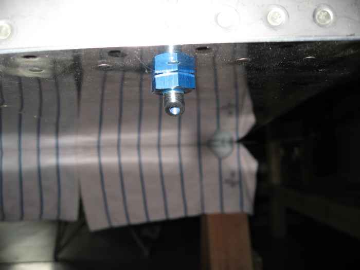
Next, a 45 degree angle was cut on the end
of the fitting using my band-saw. |
 |
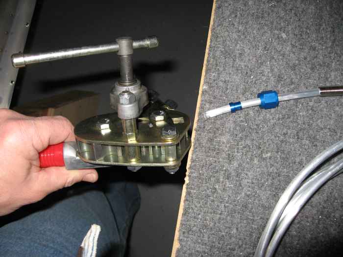
The bulkhead fittings where then installed
into the forward bottom fuselage with the 45 degree cut facing forward.
I think the purpose here is that positive pressure on the vent line will
be created by ram air. |
 |
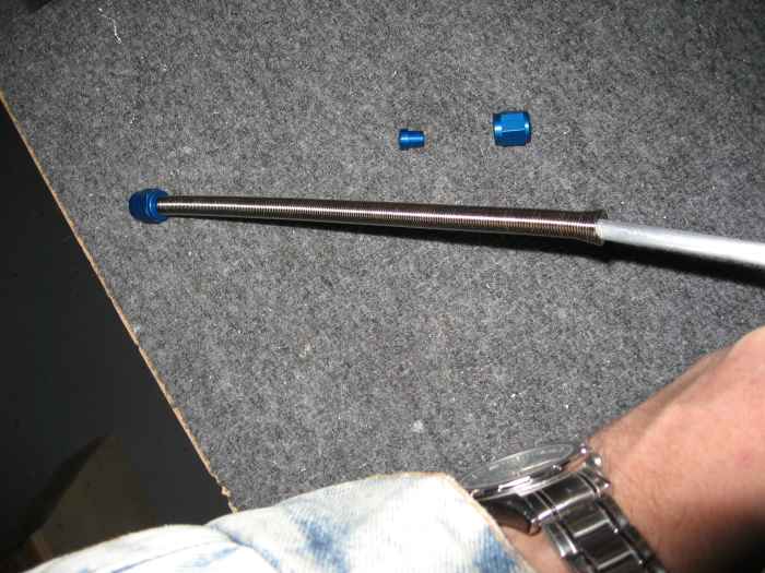
Now on to the vent line itself. It
is takes a strange bending path from the wing root area up to the
longerons and back down the firewall to the bulkhead exit.
I started by placing the fitting nut and sleeve on the tubing (do
this prior to flaring and bending!) and then flaring the end. You
need to use a special aircraft systems flaring tool that creates a 37
degree flare. |
 |
Since this is only a 1/4 tubing, I opted
for using a spring and hand bending the tubing. It worked out very
well. |
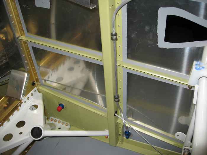 |
I started by attaching the fitting nut to
the vent inlet at the wing root, and then bending the tubing around the
lower stiffener and behind the rudder cable. Adel clamps were used
to hold the tubing in position as I continued along the path. |
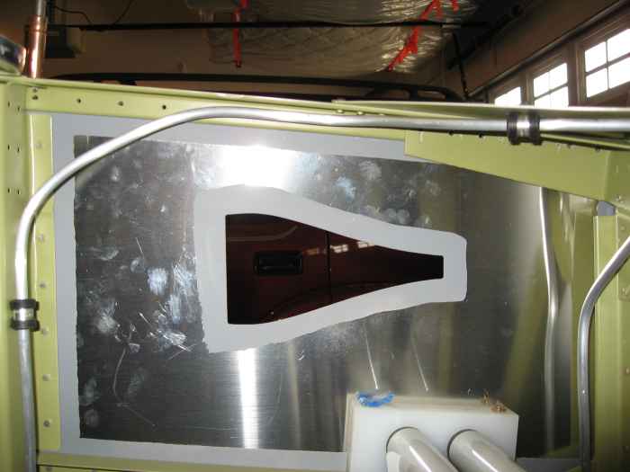 |
Here is where the tubing bends to follow
along the longeron and under the upper firewall-to-longeron gusset. |
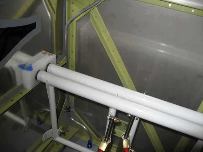 |
The tubing then travels down the inside
edge of the firewall to the lower longeron where it get held in place
with another Adel clamp. From there, it is a simple bend down to
the ventline bulkhead exit fitting. |
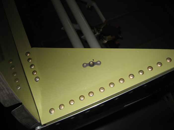 |
For some reason I did not have nut-plates
installed on the upper longeron-to-firewall gussets, so I installed
those at this time. |
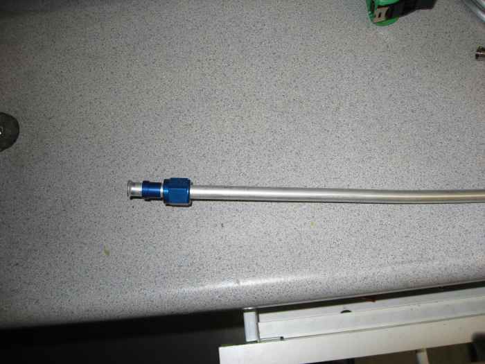 |
The fuel supply lines were the next task
at hand. The fuel line is 3/8" in diameter and much thicker
walled. I found that a hand spring bender did not work very well
on this stuff.
First things first. I slide on a nut and sleeve and flared the
end of the tubing. |
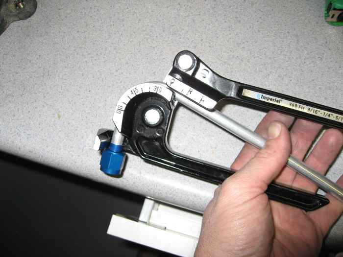 |
Using my bending tool, I created two
opposing bends as close as possible to the end of tubing.
Here I am making the first bend, which is slightly over 90 degrees. |
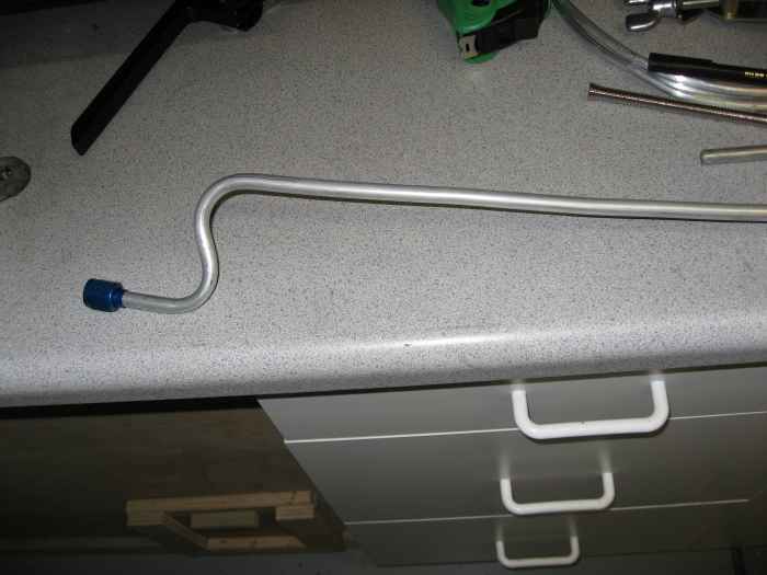 |
After the second bend is made, you should
have a 's' curve in the end of the tubing that looks like this. |
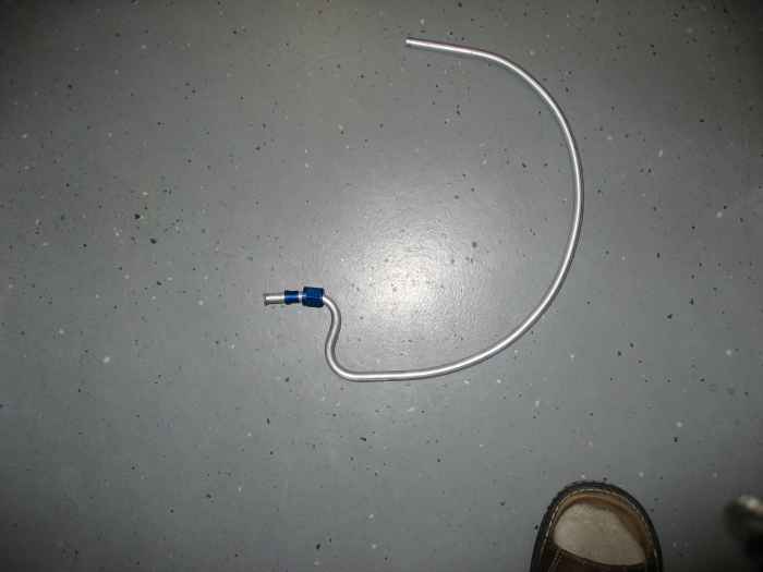 |
Next, approximate the length of tubing
required to get from the wing root to the fuel valve and cut to length.
Create a gentle curve in the remaining tubing. This curve is
required to allow you to feed the free end of the tubing through the
gear mounts |
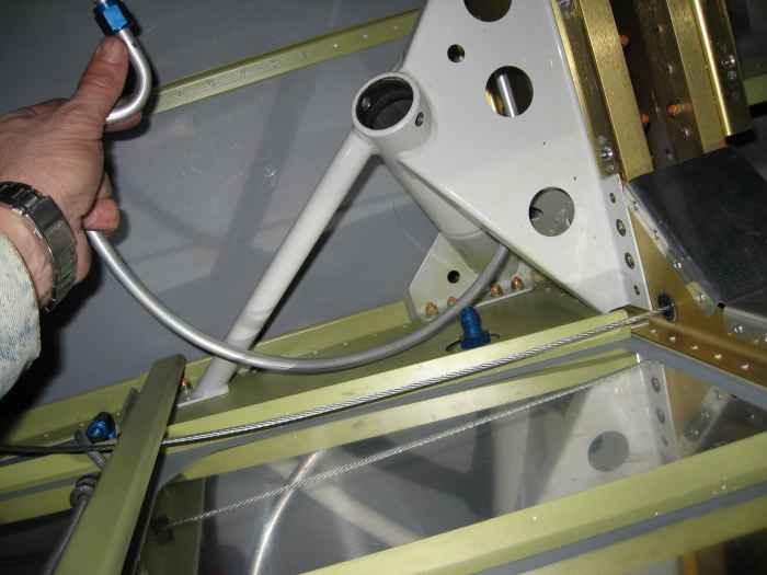 |
Hear I am feeding the the free end of the
tubing through the landing gear mount and into the lower grommet of the
front cover bracket. Once you get into this position, you will
need to use your hands to straighten the leading end of the tube a
little bit at a time as you feed it toward the fuel valve. |
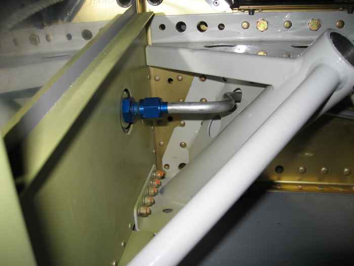 |
Eventually, the wing root end of the fuel
line will look like as pictured. This is the left side fuel line
as it passes through the landing gear mount. |
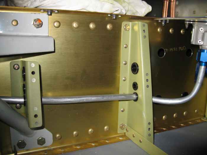 |
Here is the left side fuel line as it runs
through the forward cover bracket grommets and up to the fuel selector. |
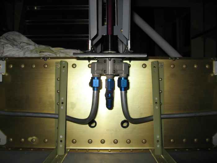 |
Here is the Andair fuel selector with fuel
supply lines attached. |
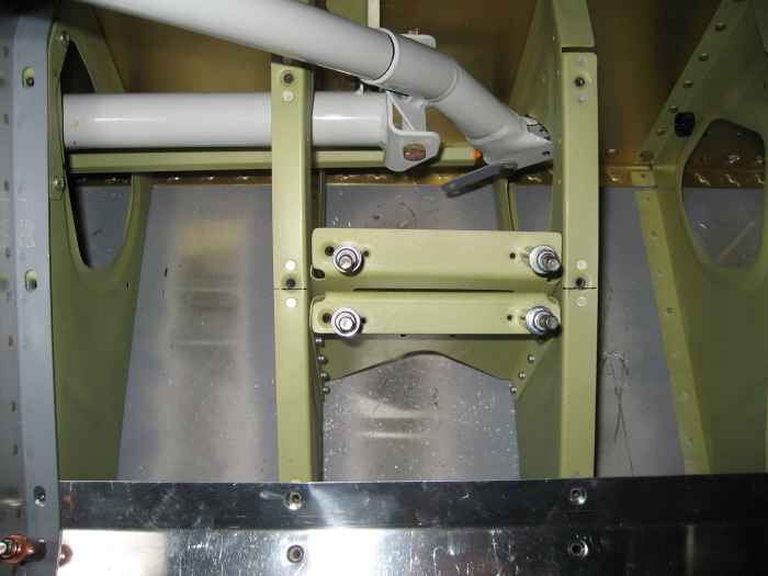 |
I had a couple of miscellaneous items to
finish up. Here I am installing the single leg nut-plates on the
seatbelt crotch-strap attach points. |
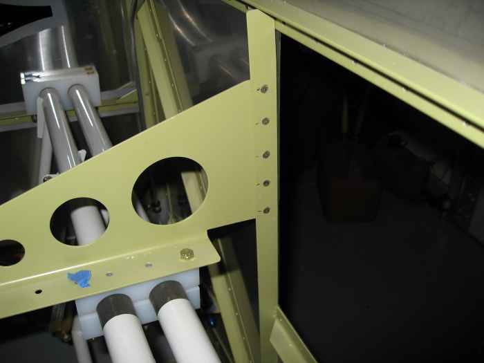 |
I riveted the rudder pedal center mount
support bracket to the firewall. |
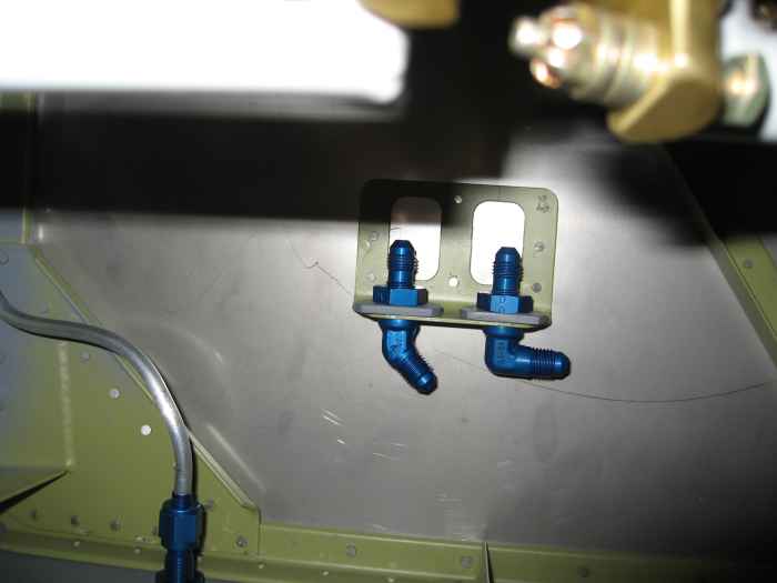 |
I wanted to get the brake lines installed,
but ran out of time. I only managed to install the AN fittings on
the firewall. |
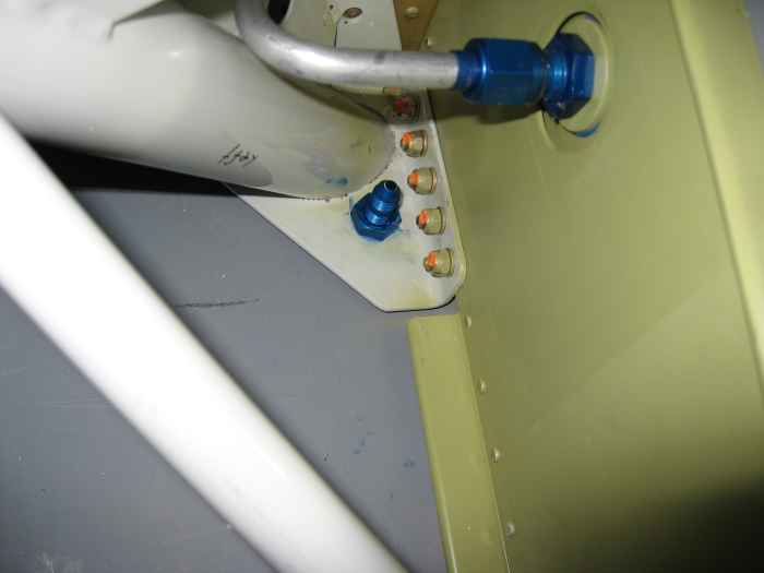 |
I also installed the brake line AN
fittings that exit the fuselage at the gear leg mounts. I
put a some RTV under these fittings to help hold them in place and seal
things up from the outside. |


