 |
September 1 - 4,
2006:
(18.0 hrs.)
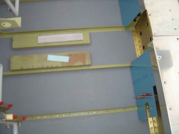
Worked on some of the forward covers in the cockpit. There are
a couple that cover the fuel lines that run along the front of the
center spar. These just need the edges deburred.
I also test fit for the forward tunnel cover and heat baffle.
The instructions indicate not to push it too far down between the center
floor stiffeners or the flanges will bend inwards and the fit will not
be ideal. I placed some wood down between the stiffeners to get
the center cover to sit at jut the right height. I am going to
wait to drill the holes for the nut-plates until I determine if I am
going to go with a center console. I am still mulling that one
over. |
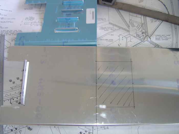 |
Since I will be going with a fuel injected
engine, I will be installing the Airflow Performance (AFP) auxiliary
fuel pump system. The kit arrived today from Vans, but had one of
the cover side walls on back-order. Not much I can do assembling
this thing until I get the back-ordered item. The standard center
tunnel needs to be modified when using the AFP. The rear portion
of the tunnel needs to be trimmed off to accommodate the AFP mount plate
(pictured on top). |
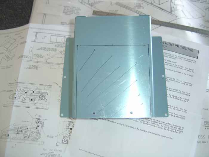 |
The standard fuel valve box also needs to
be modified. Here you can see the area I marked on the front of
the plate to be trimmed away.
That is about all I can do on the forward tunnel and covers until I
get the rest of my parts. |
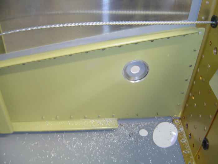 |
I decided that I was not going to go with
the standard rubber grommet for where the fuel line enters the fuselage.
It just seems like it will be a whole lot easier to bend and fit the
fuel supply lines if I put an AN bulkhead fitting in this location.
However, because the side skin and web stiffener are spaced about 1/8"
apart, the torque produced by the nut on a bulkhead fitting would tend
to bend the side skin in slightly. I did not like this, and
decided to cut a larger hole in just the web stiffener to allow the AN
bulkhead fitting nut and washer to lie against the side skin. I
drilled these holes very carefully with a hole saw and make-shift drill
stop. |
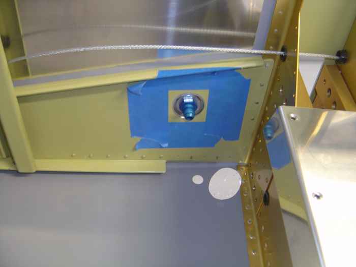 |
Here is right side with the AN bulkhead
fitting temporarily installed. This will come back out so I can
prime this area (hence the painters masking tape). |
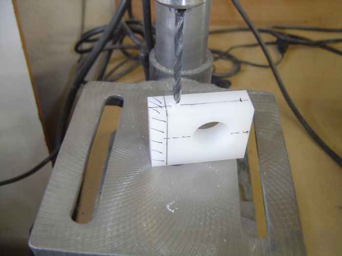 |
Now on to the flaps. The center
bushing block was drilled for its AN3 attachment bolts. The block
also need to be trimmed to length (note the marked area).
For some reason this block came a bit too long. It must be one of
those parts that is used on another RV model, and the extra length is
required. Once the length was trimmed, the block was cut in half |
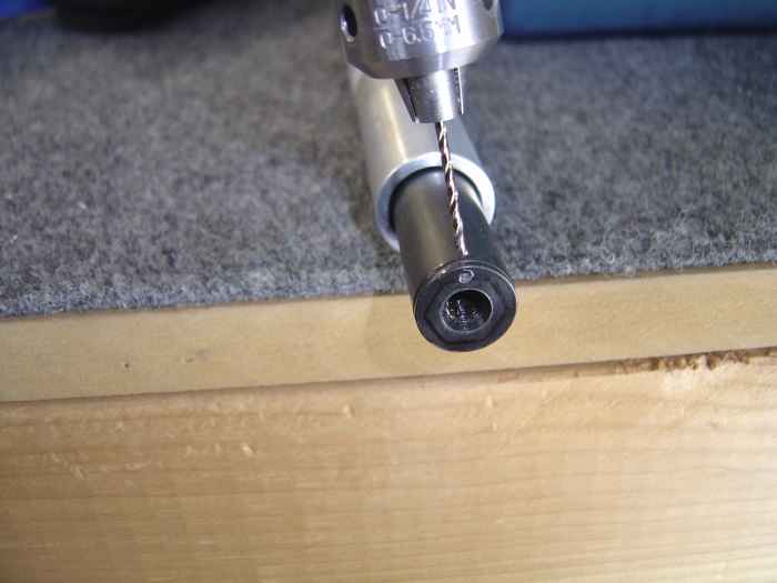 |
The very end of the flap actuator rod has
a threaded fitting than can come loose over time. This needs to be
drilled to accept safety wire. Here I am drilling the safety wire hole
thought the side wall and out the rod end. I think I was using a
#57 drill bit. |
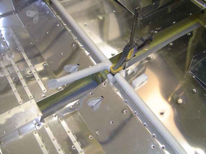 |
Fitting the flap weldmount in the cabin.
With the side bushing blocks bolted into place, I clamped and drilled
the center bushing block to the baggage floor skins and rib. This
all had to come back out (including the baggage floor skin), so I could
drill and install the nut-plates on the baggage floor rib that will hold
the center bushing block in place. |
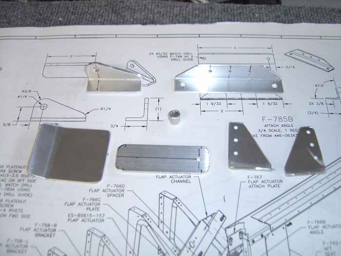 |
Fabricated all these parts that will be
required to complete the flap actuator install. |
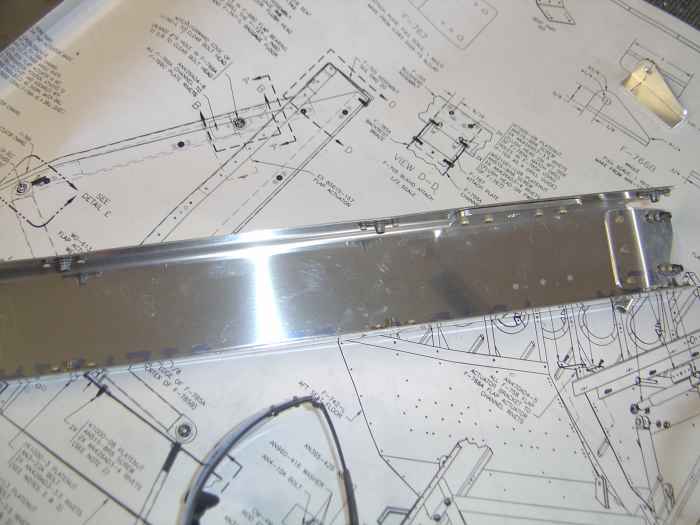 |
I deburred the forward channel edges,
riveted on the nut-plates, riveted the lower supports, and riveted the
upper channel support.
I also deburred the edges of the rear channel, and riveted on its
bottom support. |
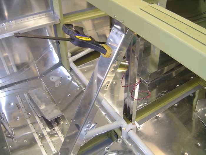 |
Here I have installed the forward and rear
channels. With the lower support of the front channel
screwed to the seat pans, the top support gets clamped and match drilled
to the F-705. Similarly, the rear channel gets screwed to the
baggage compartment floor and the top gets clamped and match drilled to
the back of the F-705.
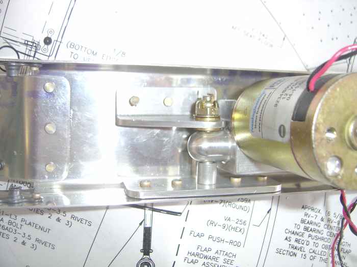
The flap actuator mechanism is temporarily bolted into the front
channel with the attachment angle fabricated earlier. Interesting
enough, the AN bolt that came with the flap assembly was too long
(something like a 20). The plans called for a 16. Luckily I
happened to have one. There was no way the longer bolt would have
worked.
Anyway, with the flap actuator at its mid point extension, the angle
bracket was clamped in place (pictured), and things were match drilled
through the forward channel. |
 |
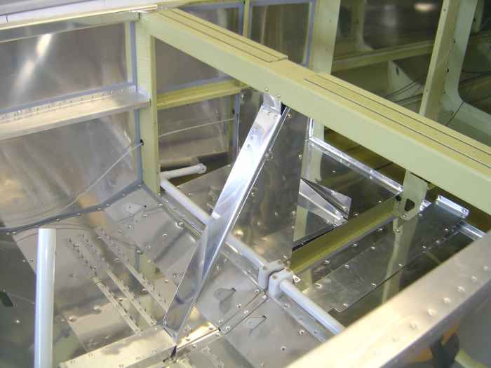
Here is the flap actuator assembly after
everything has been deburred and riveted into place. |
 |
Next, the side panels were screwed to the
front channel, and they the holes in the rear channel were match
drilled. The rear channel was then removed and fitted with
nut-plates. |
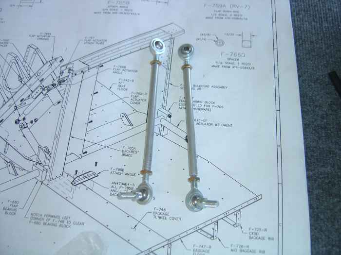 |
Fabricated the flap rods. This
entailed cutting the aluminum tubing to length and tapping the ends with
a 1/4" x 28 tap. |
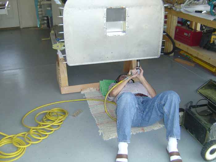 |
Remember the goof I discovered last
weekend?... The outer forward floor stiffeners were installed backwards?
Well, I drilled out all those rivets and put the stiffeners in the
correct direction. Max was in town and shot the rivets from
underneath while I reached in bucked the tails. |
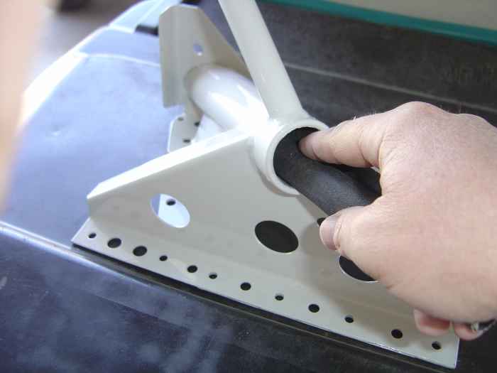 |
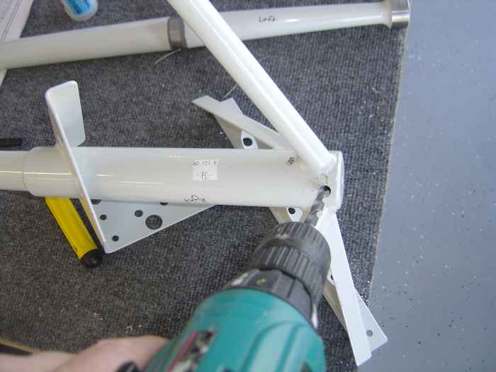
On to the landing gear weld mounts.
First, the inside of the gear tubes needed to be cleaned of any burs
and paint. I used some emery cloth to make things nice and smooth. |
 |
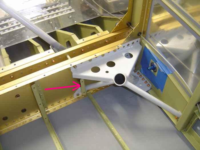
Next, the gear leg is slide into the gear
weld mount and this hole at the top of the mount is match drilled with
the gear leg to 5/16". |
 |
I then proceeded to install the landing
gear mounts. What I thought would be a simple task, turned into
several hours of work. I don't have any pictures of the process,
but basically, it required the install and removal of the weld mount
about 20 times. It is a trial and error process to get this thing
to fit. The issue is with the cut out on the bottom skin where the
weld mount must protrude. I used the Vans template to make my
cut-out, but in the end, the hole needed to be enlarged at least 1/16"
in all directions. The hole also required to be elongated
(inward). I used my dremel tool with a sanding drum to cut a
little, install the weld mount, check for fit, take out the weld mount,
cut a little, install the weld mount, check for fit, .... You get
the picture. I also found that most of the holes in the weld mount,
where the bolts pass through, needed to be slightly enlarged. I
used some drift pins to align the holes where the wings will attach,
then slide the weld mount AN bolts into position. The plans call
for AN 4-12A bolts, but these are not long enough. I used AN4-13A
bolts
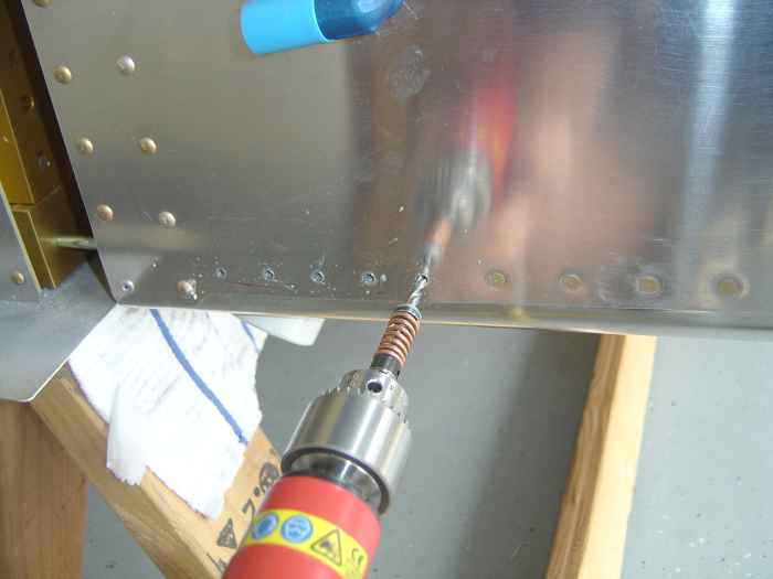
Here is a picture of left weld mount installed. The arrow is
pointing to the front cover bracket that needs to be removed when
fitting the weld mount. |
 |
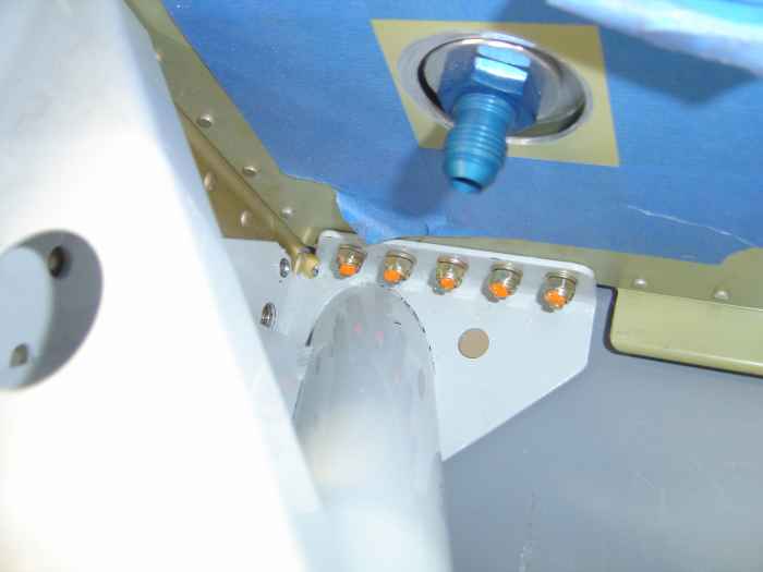
With the weld mount bolted in position on
the center spar. The attach points to the lower longeron and side
web stiffener get match drilled.
I first drilled these with a #30 bit and then moved up to a 3/16"
bit. I used lots of Boelube here! |
 |
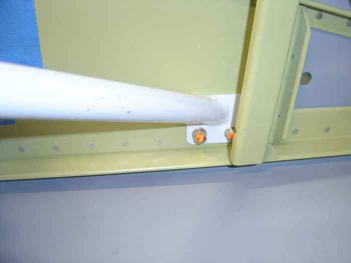
Here are the landing gear weld mount bolts
installed through the lower longeron. |
 |
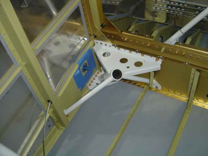
Here are the forward weld mount bolts
installed. These get match drilled through the weld mount, but
because you can only get a drill bit on the first hole, the second hole
must be measured and drilled from the outside using the first drilled
hole as a reference. The holes are exactly 1" apart on center. |
 |
Installed the right weld mount.
After knowing the process from the work on the left side, this one went
much faster. |
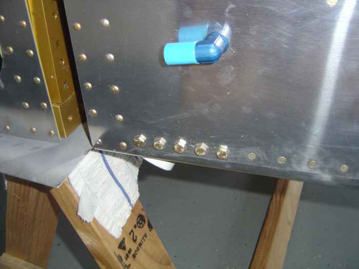 |
This is a shot of the side weld mount
attach bolts from the outside. Yes, the fuel line bulkhead fitting
is facing the wrong direction. It is only in there temporarily
until I get a chance to prime the inside skin surface where I cut the
hole for this fitting. |


