 |
March 30 - April 1,
2007:
(4.0 hr)
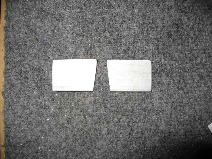
More work on mounting the horizontal stabilizer. I fabricated
these spacers that sit underneath the forward spar of the horizontal
stabilizer. |
 |
After putting the spacers in place, I
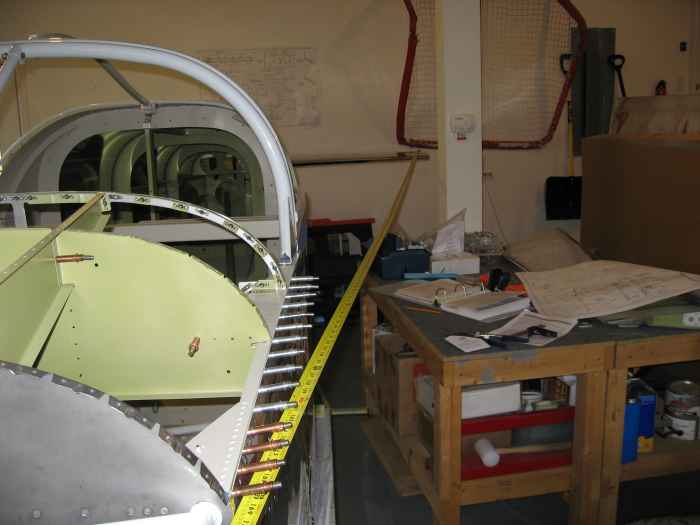
spent a lot of time getting the position of the HS perfect. I
measure another dozen time from the rear tip of the HS to the front of
the firewall on each side. Pictured is my tape measure out
stretched from HS rear tip to firewall. |
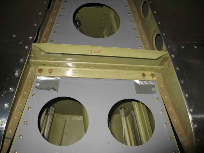 |
I held the spacers in place using duct
tape and then drilled the front spar of the HS through the aft deck and
longerons using my right angle drill attachment. You need to
measure carefully for where these holes get drilled so they hit dead
center of the longeron and the F-711 bulkhead attachment angle.
This is a picture after I drilled the holes and slipped in the bolts. |
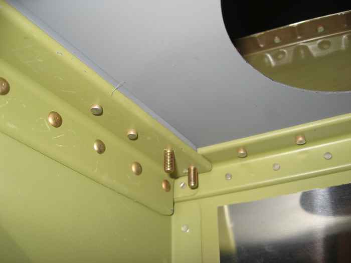 |
Here you can see the bolts extending down
into the fuselage. The outer bolts hit dead center of the
longeron's while they were a bit forward of the F-711 bulkhead
attachment angle. I still think the edge distance on these is ok. |
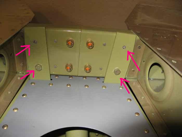 |
After checking all my measurements again
to make sure nothing moved, I drilled the rear spar attachment holes
using the holes in the attachment straps as drill guides. |
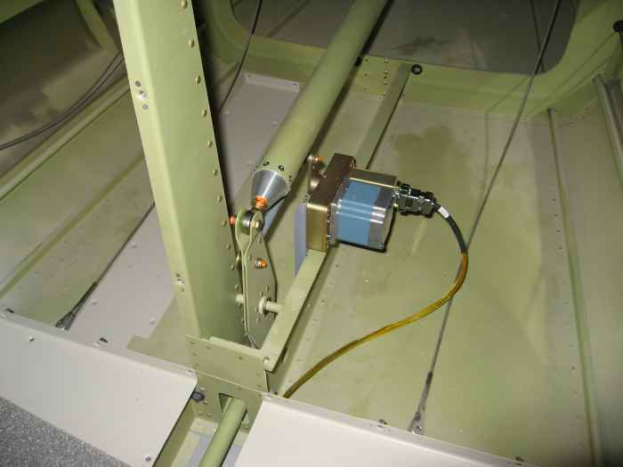 |
I had prior made the elevator control rod,
so all I had to do was hook it up to the bell crank and position the
bell crank in the vertical position (neutral). |
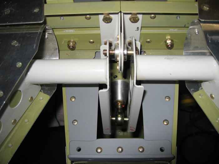 |
I temporarily installed the elevator
halves and hooked up the elevator control rod to the elevator horns.
I will need to fabricate some spacers or use washers on either side of
the rod-end bearing to take up the excess space. For now, just the
bolt is in there. I got lucky and my elevator control rod length
was spot on. I did not have to make any adjustments to it to get
the neutral position as specified in the instructions. |
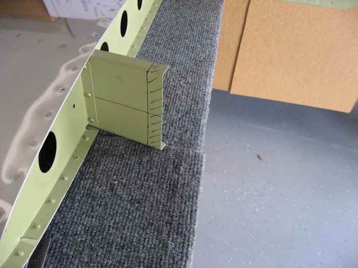 |
Next, I pulled the vertical stabilizer and
rudder down from the ceiling and cleaned the 2 years of dust off them.
I also removed the blue plastic from the skins.
I marked and trimmed 5/8" off the front spar of the vertical
stabilizer. My Wiss hand snips made quick work of this. I smoothed
all the edges with a Scotchbrite wheel in my die grinder. |
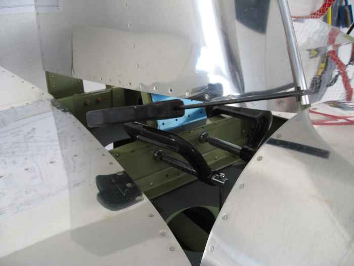 |
I clamped the vertical stabilizer into
place and measured from its tips to the tips of the horizontal
stabilizer to make sure it was perfectly vertical. |
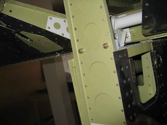 |
Once I was comfortable with its position,
I drilled two holes in the rear spar that attach the vertical stabilizer
to the elevator stop. The holes in the elevator stop are used a
drill guide. I had to again use my right angle drill attachment to
get into the tight space.
Here the two bolts have been temporarily installed. |
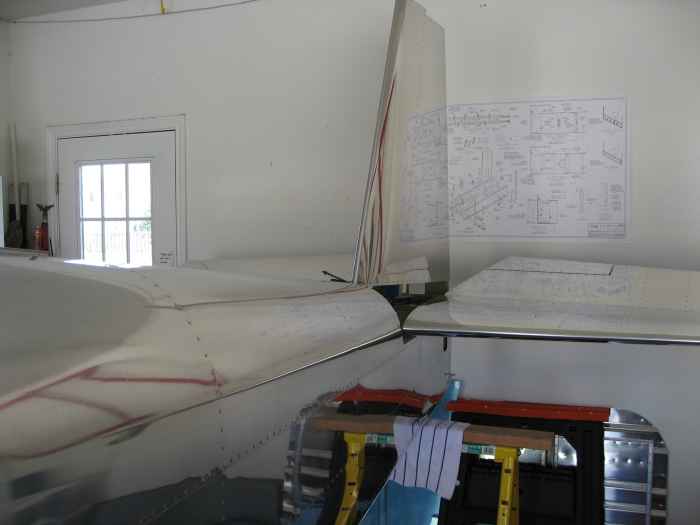 |
Here is a picture of the tail section.
Upon seeing this progress, my youngest son (4 years old) remarked with
excitement; "That is cool! Your airplane is so cool Daddy".
I think seeing the tail installed made something click for him where he
could now finally visualize what I was building. He finally gets
it. That was a great moment and something I will always remember.
I still need to finish mounting the vertical stabilizer and
rudder, I will complete that during my next working session. |
 |
April 6 -
8:
(5.0 hr)
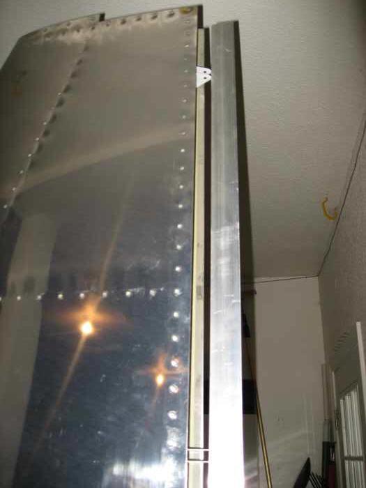
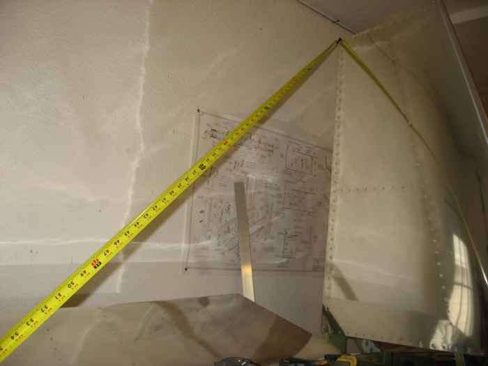
Before securing the forward spar of the vertical stabilizer, it is
key to ensure the rear spar is completely plumb. The easiest way
tot do this is use a piece of straight stock material (I used some
aluminum angle), and run it along the rod end attachment joints for the
rudder. Once you have it plumb, you can clamp down the forward
spar. |
 |
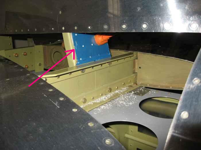
After clamping the forward spar, I next
measured from the top of the vertical stabilizer to each tip of the
horizontal stabilizer to make sure I was still perpendicular. When
you do this measurement, you have to use the top rear of the vertical
stabilizer and NOT the top leading edge! This is because, if you
have mounted the vertical stabilizer correctly, the leading edge should
be offset about 1/4" to the left of the fuselage.... So, using the top
leading edge for your measurements would naturally lead you to different
dimensions on each side. |
 |
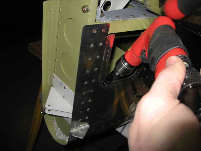
Here I am match drilling the holes from
the vertical stabilizer forward spar attach plate into the vertical
stabilizer forward spar. I had to introduce a 1/8" shim between
these two surfaces to get the vertical stabilizer to be truly vertical.
I guess this is nothing unusual, because it is called out in the plans. |
 |
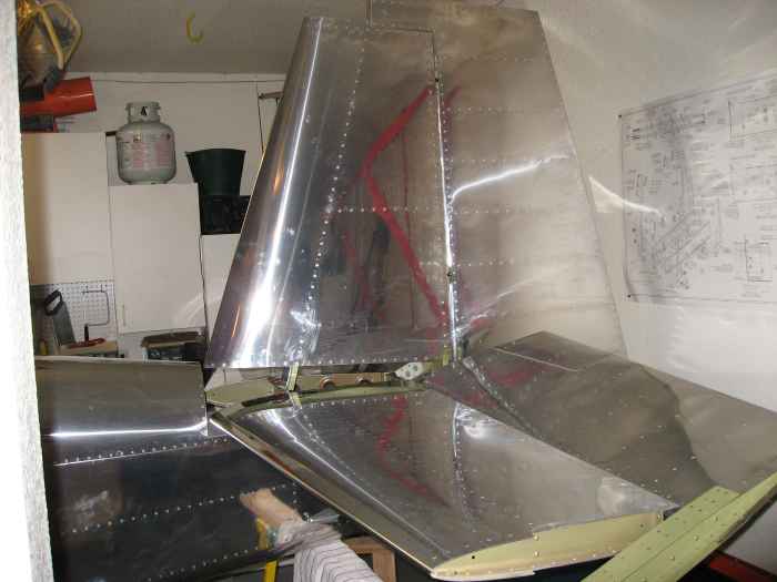
Next, I had to drill the 4 bolt holes
through the bottom of the vertical stabilizer's rear spar. These
get matched drilled via holes that were drilled prior in the tail
tie-down. This presented an access issue since the tail tie-down
was already riveted into the tail cone.. I had to use my right
angle attachment and drill in the blind through the aft fuselage access
point. This was a real pain the behind. |
 |
I installed the rudder and made a few
adjustments to the rod-end bearings lengths to get smooth rudder
movement and the minimal gap between the vertical stabilizer and ruder
surfaces. |
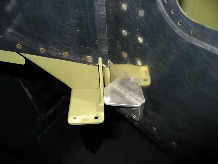 |
I had previously fabricated and installed
these rudder stops. That turned out to be a bad idea!
Although, as the picture shows, they work very well, they allowed to
much rudder movement. The plans call for 35% to both sides.
I ended up drilling these out and fabricating a new set. |
 |
September 19-30,
2007:
(1.0 hr)
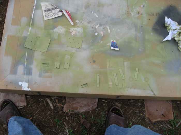
Removed the empennage from the fuselage. Deburred, cleaned, and
primed all the parts that I had only match drilled prior.
Hard to see, but this is a bunch of parts painted primer green. |
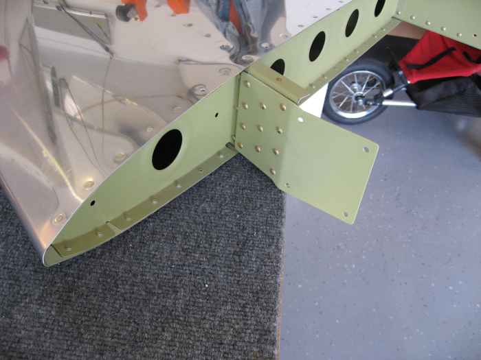 |
I riveted the attach plate and spacer to
the vertical stabilizer. This can now be stored away. |
 |
February 2-9,
2008:
(2.0 hr)
I hear that sealing off the area where the aileron push rods enter
the fuselage really helps in keeping the interior warm, so I decided
fabricate and install some aileron boots.
Some mounting plates were cut out of .040 aluminum to match the
openings on either side of the fuselage. Next, the fuselage was
drilled for four nut-plates to hold the mounting rings in place. I
decided to put the nut-plates on the inside of the fuselage and have the
screw heads on the outside. I could of done it the other way
around... I do not think it matters much. Either side will be
accessible if I need to replace the boots.
|
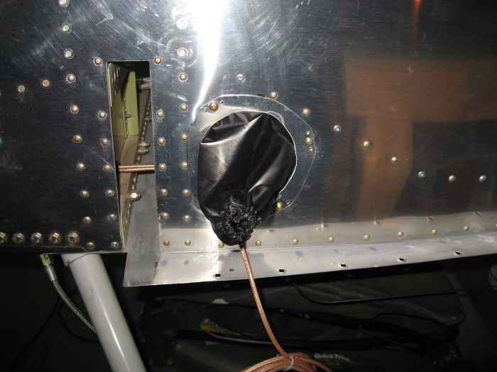 |
Here is the mounting ring and aileron boot
installed on the left side. I bought the boots pre-made from Abby
at FlightLine Interiors (http://www.flightlineinteriors.com/).
They would have been simple to make, but I have enough stuff to do and
did not want to deal with sewing. I added some RTV between the attach
ring and the fuselage to get a nice tight seal. |
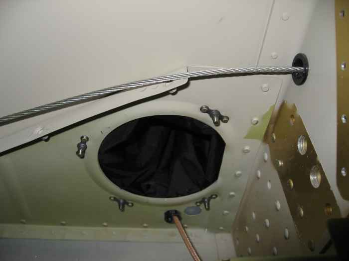 |
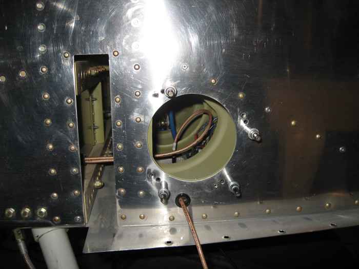
Here is gratuitous shot of the inside and
the nut-plates. |


