 |
October 13, 2006:
(1.0 hrs.)
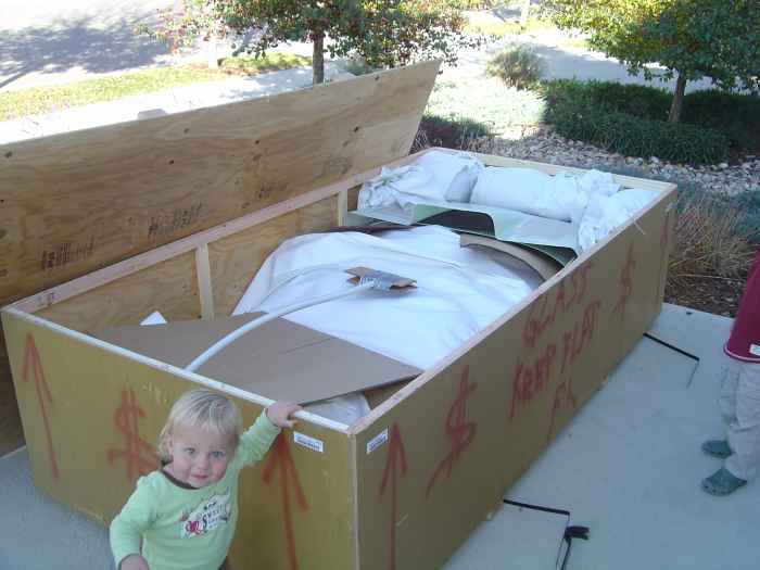
The finish kit arrived today. I immediately
cracked the crate open and began to inventory the parts. There are
not as many parts in this kit as the fuselage and wing, so things were
pretty easy to inventory. |
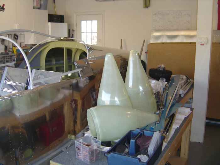 |
Bunch of the finish kit parts piled on my
work benches and laying on/in the plane. I need to a place to
store this stuff so I have room to work. I think I will move the
canopy and fiberglass components to the basement until I am ready for
them. |
 |
January 1-7,
2007:
(5.0 hr)
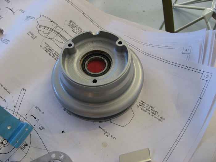
Began assembly of the main wheels. These come packaged in
the Cleveland brake kit. The wheels have an integrated disk brake.
First thing to do is separate the wheel halves and inspect the
bearings and that they are greased. Mine were well greased. |
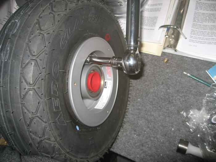 |
A tube is placed in the main tire (talcum
powder in the tire will help the tube seat itself when inflated).
The tire is then slide over the wheel halves, which are then bolted
together. The only thing to pay attention to here is that the
valve stem aligns with the red dot on the tire. Once things are
bolted up the tire is inflated. |
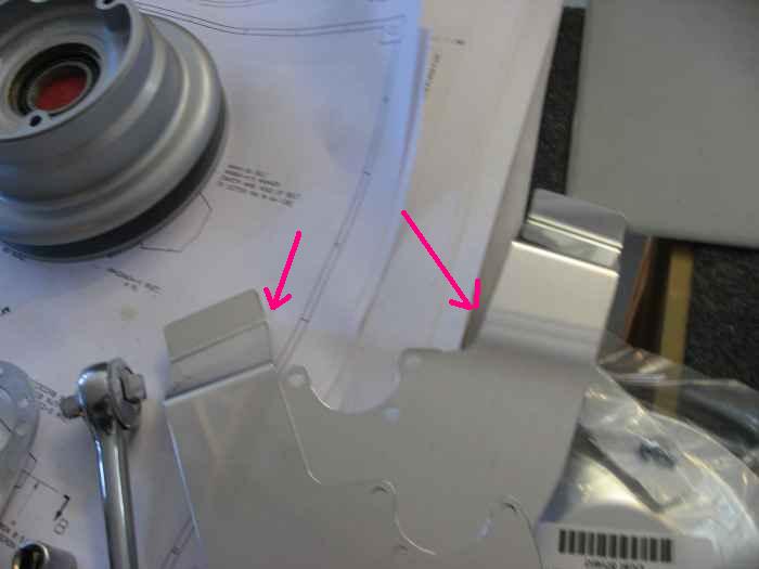 |
The kit comes with some aluminum wheel
pant brackets. I cleaned up the edges on these using my
Scotchbrite wheel. These get installed with the rest of the wheel
assembly. I will most likely replace these with some stainless
steel aftermarket brackets. I have heard that aluminum brackets
tend to crack.
Hard to see, but hear are the two inside wheel pant brackets laying
on my work bench. |
 |
The plans are not the greatest on how the
brakes are assembled on the mains. After much head scratching and
trial and error, I finally figured it out.
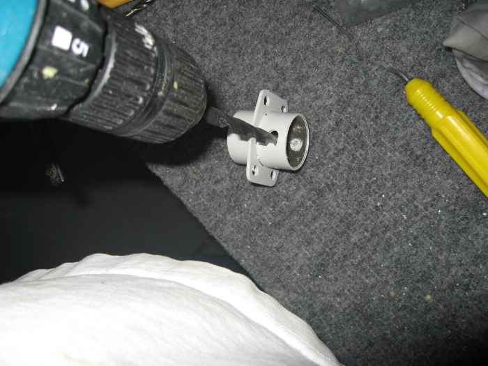
First you need to enlarge the holes in the brake flange (where it
attaches to the main axel) to 5/16". |
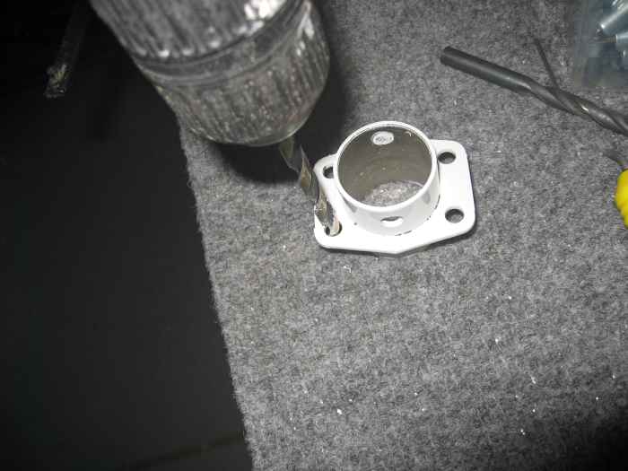 |
While you have the drill out, switch bits
and clean the powder coat out of the AN4 attachment holes |
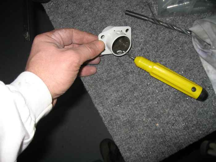 |
Next, debur all the holes and use some
emry cloth to clean out the inside of the brake flange |
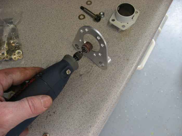 |
Next, you need to make the Cleveland brake
mounts fit over the brake flange. I had to use my dremel tool,
followed by some smoothing with a ScotchBrite wheel on my die grinder,
to get it to fit. |
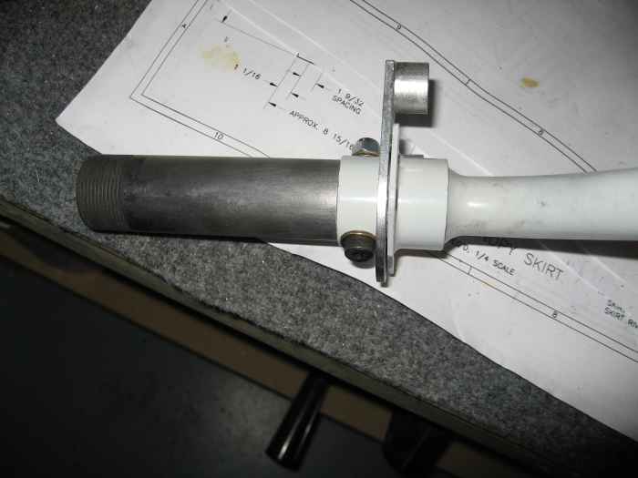 |
Here I have installed the brake flange and
Cleveland brake mount onto the main axel. Note the bolt that goes
through the flange and main axel has a allen head. It took me
quite a while to find these bolts. Turned out they came in the
fuselage kit and not the finish kit. |
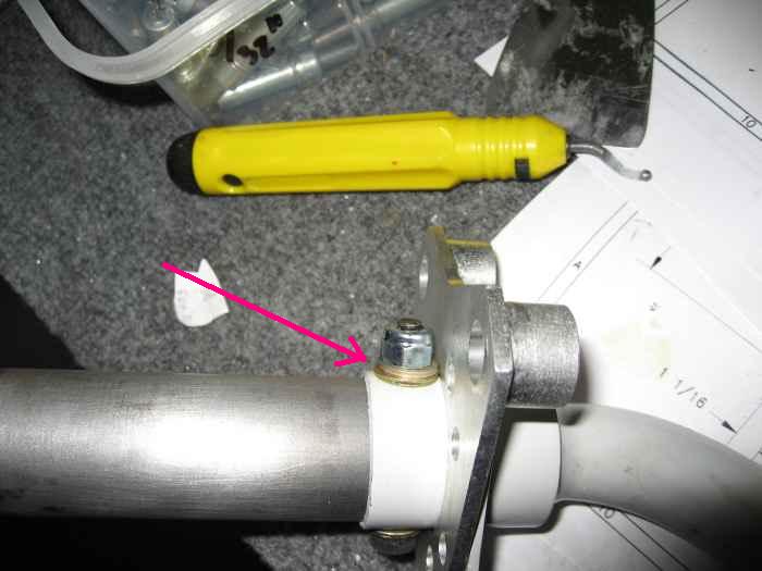 |
Here is picture of the back side of the
brake flange. Kind of hard to see, but there are two different
size washers under the lock nut (AN6 and AN4 I think). This is to
accommodate the change in size between the bolt diameter and the threads
on the end. |
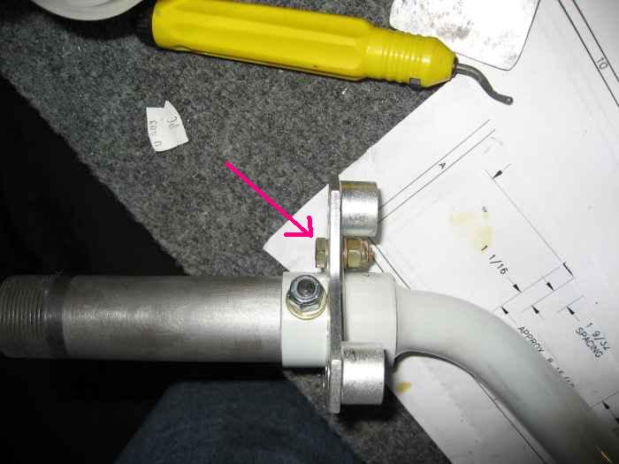 |
Looking from the rear, you can see the one
AN4 bolt that holds the Cleveland brake mount to the brake flange. |
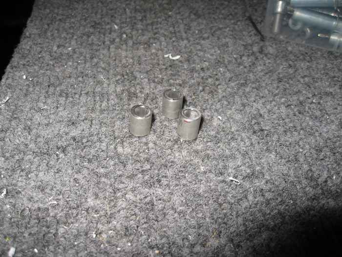 |
Next, three spacers (per side) need to be
fabricated. These are used to offset the interior wheel pant
bracket the correct distance from the Cleveland disk brakes. |
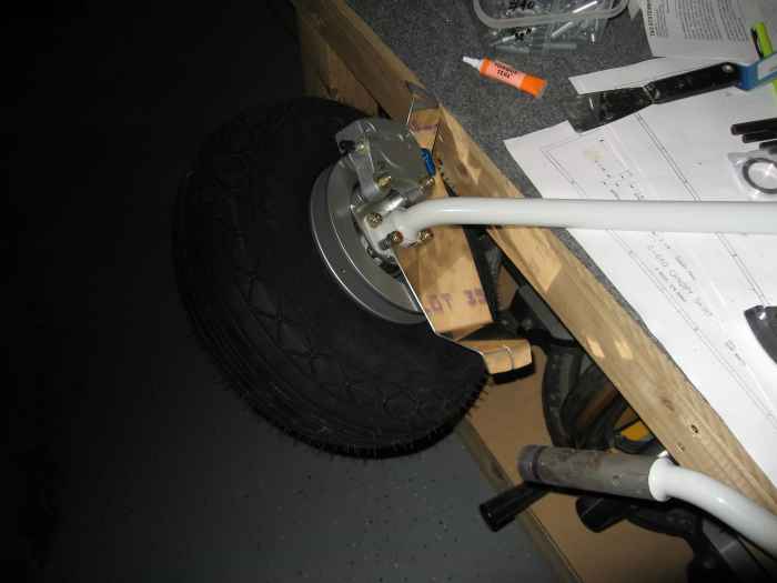 |
Here the interior wheel pant bracket,
wheel, and brake have been installed. You need to make sure you
have at least 1/16" of clearance between the wheel pant bracket and the
disk brake. If you do not, you can shim with washers, or fabricate
new spacers (shown above) as appropriate. |
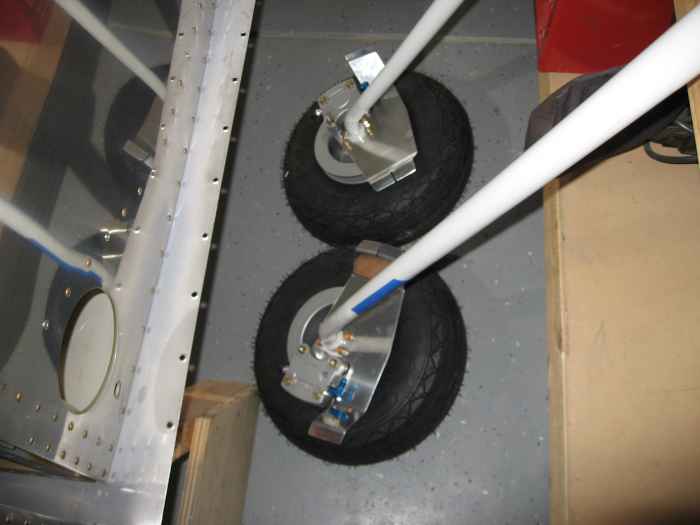 |
Both left and right side complete. |
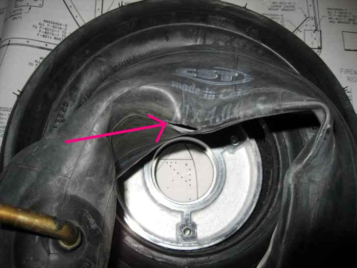 |
Next, I moved on to the nose gear.
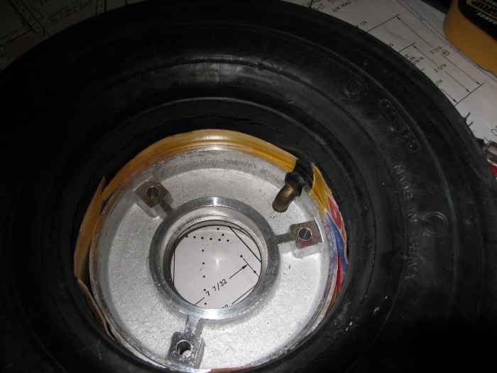
This wheel is a pain to put together, and if you are not careful, you
can pinch the inner tube with the wheel halves. This is what
happened to me! |
 |
Luckily, Vans shipped me two tubes.
I am not sure if this was a mistake or standard practice. After
some research, it turns out lots of people have problems trying to
assemble the nose wheel. I did learn a few tricks on my second go
around. 1) Get on wheel half squeezed into the tire as far as possible
before beginning
2) Insert the inner tube and partially inflate it to keep it from laying
over the wheel half
3) Use a strip of thin plastic or cardboard (i used this) as a liner
between the wheel halves and the tube
In the picture, the yellow is a strip of thin cardboard used to
separate the wheel halves from the tube. This was the critical
factor in avoiding pinching the tube when the two halves came together. |
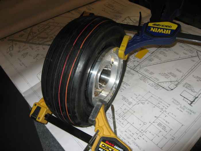 |
Next, use a couple of clamps to bring the
halves together and allow for easy install of the bolts. |
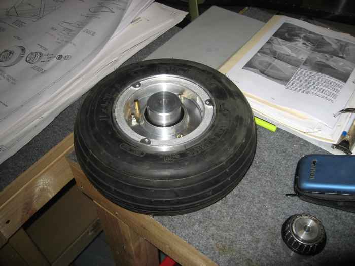 |
When all was said and done, I had a leak
free nose wheel the second go-around. The bearings for this wheel did
not come pre-greased, and I do not have any grease on hand. I will
have to order some grease before I can finish this wheel up. |


