 |
June
30 - July 3, 2006:
(10 hrs.)
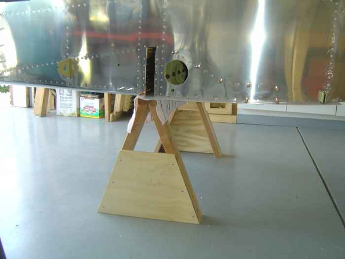
Built these saw horses at 21.5" tall to support the fuselage center
section. At this height, I was able to use a standard saw horse
under the tail. Once the fuselage was stable, I removed the seat skins
and set the remaining rivets holding the outboard seat ribs to side
skins. Because I am using nut-plates to attach all the seat
bottoms, there were a few places where I did not have access to buck the
tails of solid rivets so I just used blind rivets. These will not
be visible when the wings are attached. |
 |
There were a bunch of little odds and ends
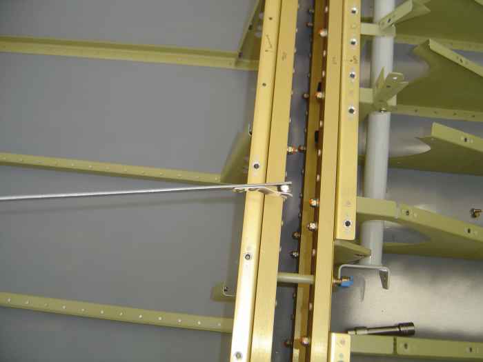
for me to take care of... I decided to install the control stick
assemblies I had built earlier. The brackets that attach to the
aft F-704 require a washer and nut to be installed on the AN bolt in
between the F-704 assemblies. There is not enough room to reach a
hand in between the two F-704s. I used my washer holders
(available at Avery's) to place the washer, followed by the nut holder
(pictured). |
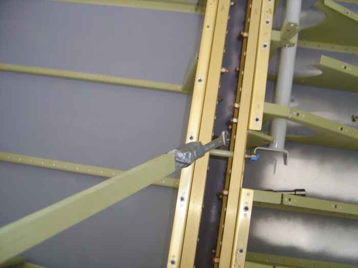 |
I used duct tape to hold a box-end wrench
on the end of a long stick so I could reach in between the F-704s and
hold the nut while I torqued the bolt end. |
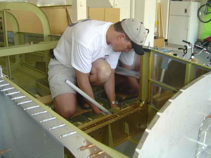 |
Here I am in the plane for the first time.
To attach the control stick hardware, I need to get up and close.
I am glad I spent $30 to purchase the washer holders from Avery Tools.
These have proven to be invaluable, especially for the control stick
hardware where I needed to place several washers in a tight space. |
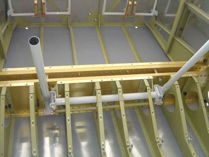 |
The final product after several
adjustments to get the sticks completely parallel.
I also took advantage of having the seat bottoms off to install a few
more nut-plates that I did not get the first time. |
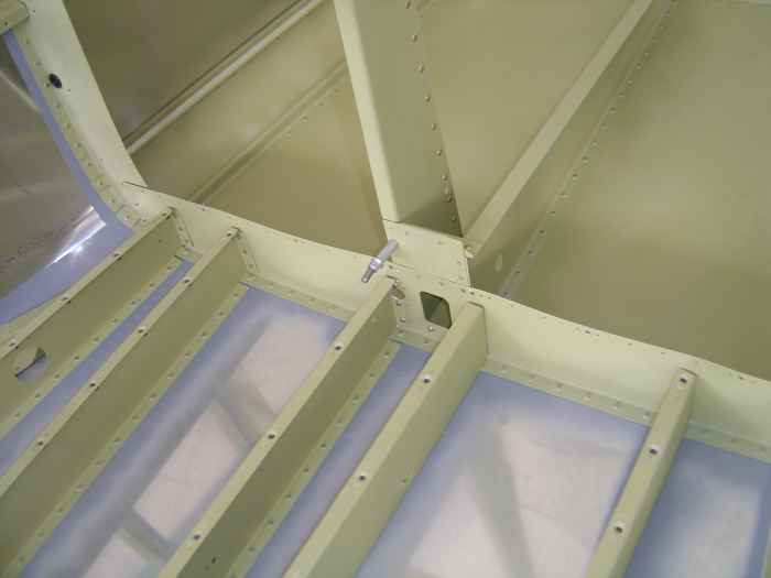 |
Miscellaneous work continues... I set the
AN470 rivets that attach the baggage compartment ribs to the F-706 |
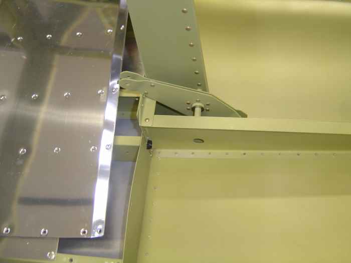 |
Some time back I had already build the
elevator bell crank, now I was finally able to install it. (those
of the seat bottoms just laying in the baggage compartment) |
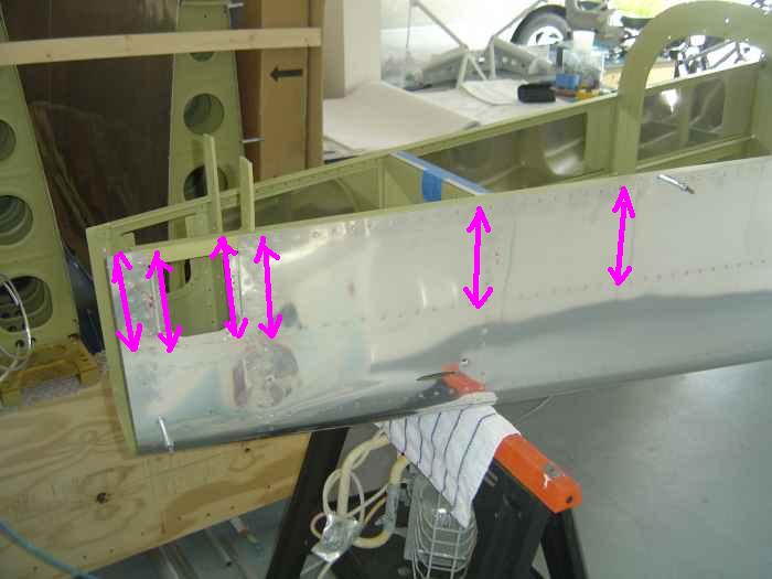 |
I shot all the remaining bulkhead to side
skin rivets on the left and right side of the aft section. |
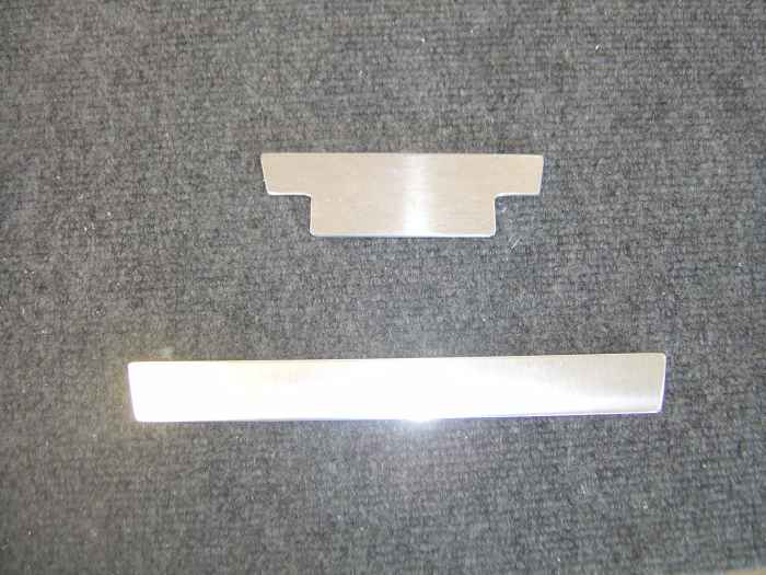 |
Before I can begin fitting the aft deck, I
needed to fabricate these spacers that will sit underneath the deck. |
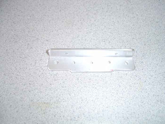 |
I also went ahead and fabricated the
elevator stop. Seems like it would be easier to build and fit this
during the aft deck assembly. |
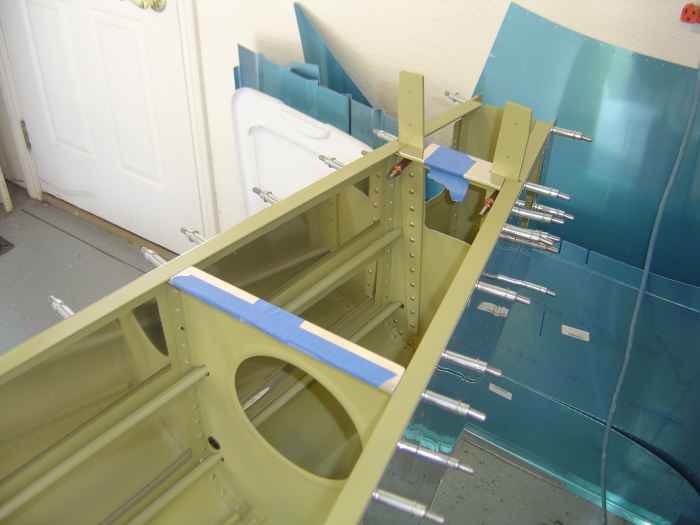 |
Here are the spacers taped in place so the
wont move while match drilling the aft deck. |
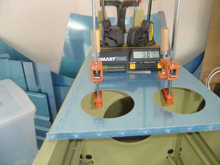 |
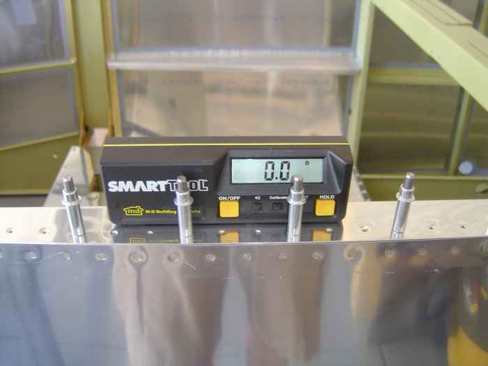
Aft deck gets clamped in place and
everything is checked for level. With a little adjustment and some
tightening of the clamps, the digital protractor reads level (0.0) |
 |
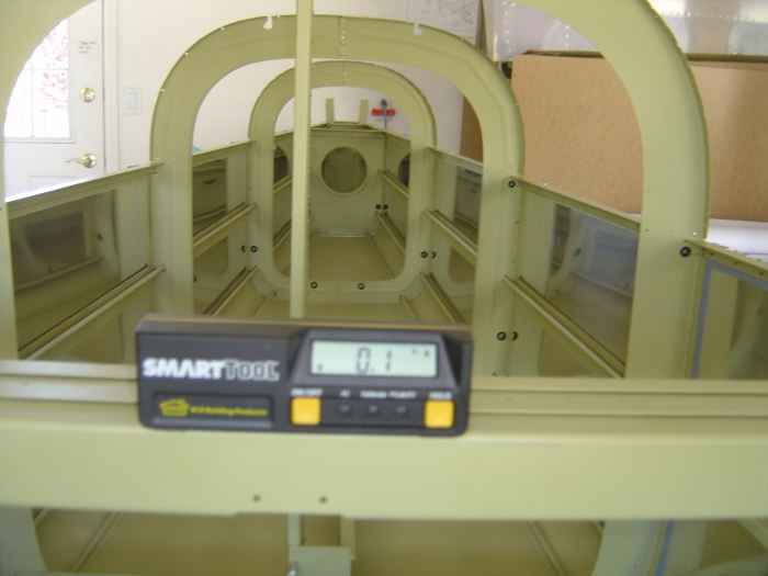
The longerons at the center section should
also read level. If they do not, then some shimming is necessary.
To avoid any twist in the fuselage, it is critical everything is square
prior to drilling the aft deck. |
 |
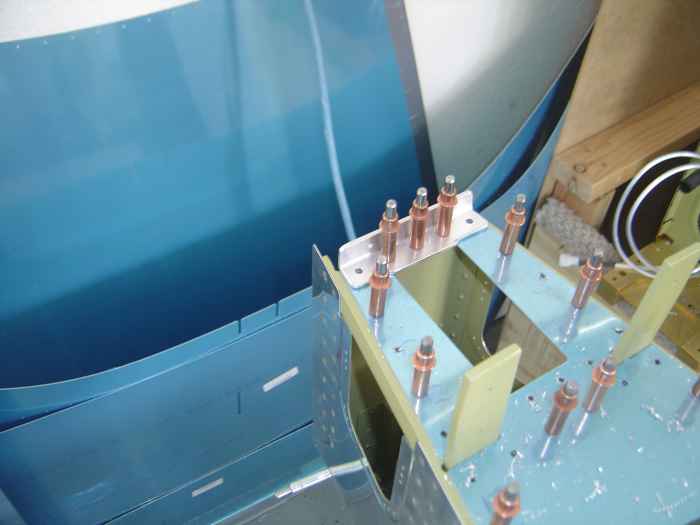
Here I am checking for level across the
seat back. It is close but not perfect. However, I found
that because the F-705 is still not completely attached to the fuselage,
it is not the best thing to use for leveling across the longerons.
I ended up placing a level across the longerons as at the center section
and then putting my digital protractor on it. I got things to
level out completely (0.0) in this fashion. |
 |
With things level and plumb, I drilled the
aft deck |
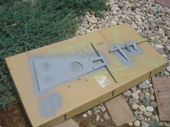 |
After a deburring session, I primed these
parts using the Napa self etching primer. Since these parts all
had a nice Alclad finish, I did not think it was necessary to use the
AKZO primer. |
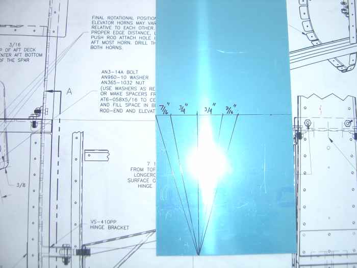 |
I figured it would probably be best to
address some of the aft fuselage work prior to installing the aft deck
because of the easier access.
Here I am laying out the rudder cable exit fairings. This
.20" aluminum will be cut out and bent on the lines to form the first
fairing. |
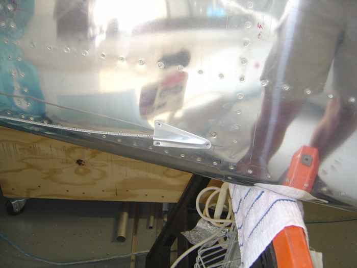 |
Here is the fairing completed and
installed. |
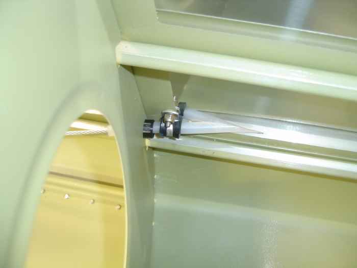 |
I also ran the rudder cables and secured
them in the specified location per Vans. This is a shot of the
inside of the aft section where the right side rudder cable exits the
fuselage. |
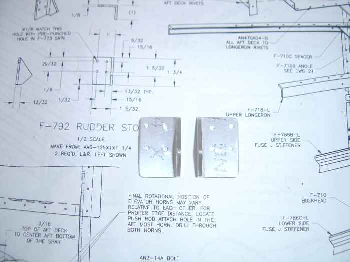 |
Next I fabricated and installed these
rudder stops. |
 |
Here is the right side rudder stop
installed. |


