 |
September 23-24,
2006:
(4.0 hrs.)
I have been away from the project for about two weeks because of work
related travel. It seems like there are a million little things
that need to be worked on. I decided to work on the seat belt
crotch strap. This is an add-on component to the Vans kits that I
think is well worth it. Adding the 5th point to your seat belt
system can add to the survivor-ability of a crash, especially if it is a
flip over.
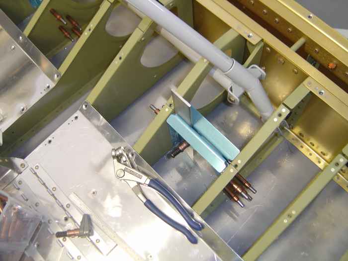
Installation amounts to installing these two pre-fabricated plates
between the seat bottom ribs on both the left and right side. The
plates need to be 1/8" apart to allow the seat belt end to insert
between the plates and get fastened down with a bolt. I used a
scrap piece of aluminum as a 1/8" spacer while I clamped and drilled the
parts to the seat bottom ribs. I had to make use of my right angle
drill attachment to match drill the holes in the crotch strap plates to
the seat ribs. I then removed the parts and deburred the holes and
edges. These will get primed during my next painting session, then
I can rivet them into place. |
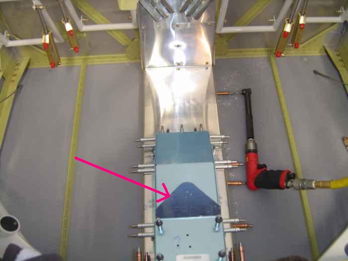 |
I finally received the back-ordered side
skin for the AP fuel pump cover. Now I could finish the cover
assembly. I cleco'd all the parts together in the cabin and match
drilled the holes. The right angle drill attachment had to be used
to drill the holes through the floor stiffeners into the center tunnel
cover.
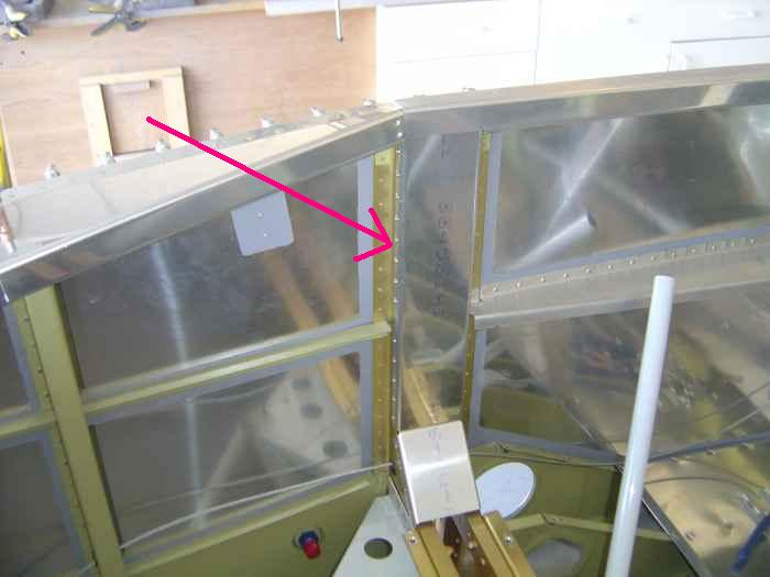
The arrow in the picture is pointing to the area on the fuel valve
cover plate that is supposed to be used to mount the manual elevator
trim. Since I have installed electric trim, this section of the
cover plate can be removed. |
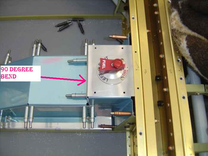 |
Since I was not going to be using the
stock fuel valve, what worked out nicely on the fuel valve cover plate,
was to bend the manual trim mount area from its 30 degrees position to
90 degrees and then cut the section off leaving a 1/2" flange. The
cover plate was flipped upside down and mounted to the AP fuel pump
cover. The small bend and flange on the cover plate serves to
close any gap that would have existed if the manual trim area were just
completely removed. I chose to install an Andair FS 20x7T over
the stock fuel valve. The valve has positive locks while in the
left and right position. This will prevent any accidental bumps
switching the fuel supply off. Since I am planning on installing a
center console that attaches to the panel, I will need to get an
extension for this valve so it can be operated from the center console. |
 |
Next, all the forward covers were removed.
The edges and holes were deburred. Rivet holes were dimpled and
the parts riveted. I had to use the pneumatic rivet gun on some of
the rivets. Nut-plates were also installed.
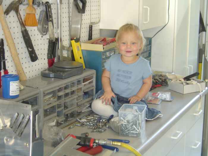
My daughter Katy was having fun with the cleco's while I worked at
the bench. |
 |
September
29 - October 1, 2006:
(4.5 hrs.)
Worked on several miscellaneous items this weekend.
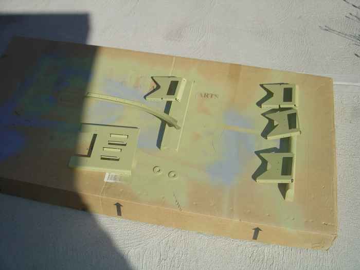
Prepped and primed the crotch strap parts, the AP fuel pump base, and
one of the aft top skin stiffeners. |
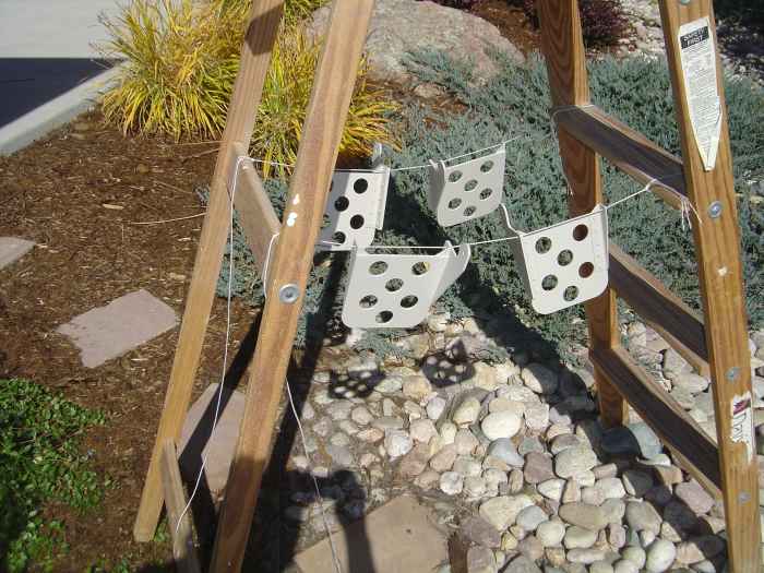 |
I also painted the brake pedal with
JetFlex water soluble paint. This is a special aircraft interior
paint avaialble from Sherwin-Williams. It is hard to tell from the
picture, but this is a grey/beige color. Should match nicely with
the beige leather seats I plan to install. |
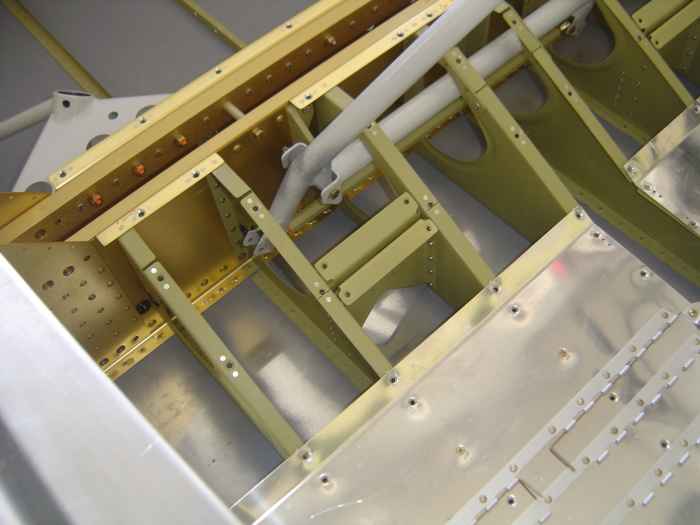 |
Riveted the crotch strap attachment points
into place. These took simple blind rivets. |
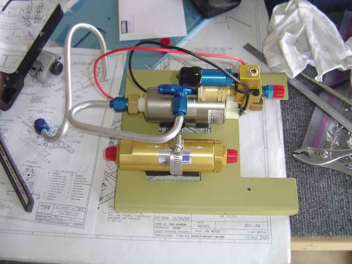 |
Mounted the AP fuel pump and filter to the
base. I also began to run the numerous tubes that this system
requires. This was really my first take at tube bending.
Needless to say, I made a lot of mistakes an need to order some more
tubing. |
 |
Installed the F-704 side cover plates.
This amounted to match drilling all the holes, deburring the holes,
deburring the edges, and blind riveting them into place. With
these in place, I am getting fairly close to the point of painting the
interior. |
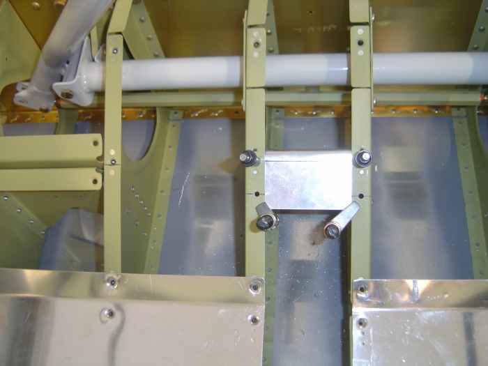 |
Started fabrication and installation of
the aileron trim control. Here I am fitting and drilling the
support plate between the center seat ribs. |
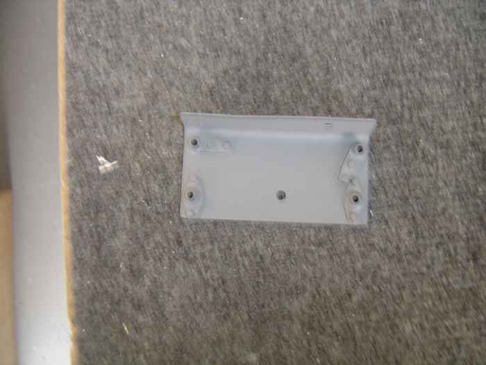 |
The support plate is then match drilled
and fitted with nut-plates. I primed this part using the
rattle-can primer. |


