 |
May 3, 2005:
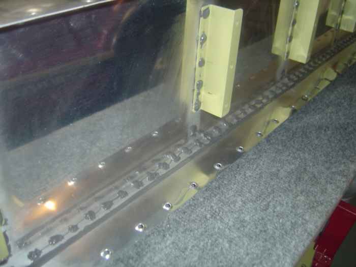
(1.5 hrs.) Mixed up another batch of ProSeal and covered the shop
heads of all the rivets on the rear baffle |
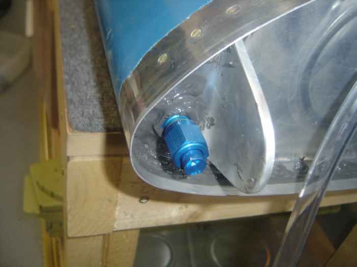 |
I ordered the tank test kit from Van's.
It comes with this end cap for the for the fuel pick up line.
Before attaching it, I put some EZ Turn on it (substitute for Fuel
Lube). This will help ensure a good seal. |
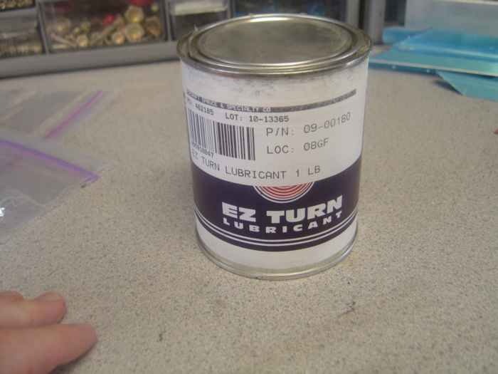 |
This is the can of EZ
Turn I purchased from Aircraft Spruce. You don't have to use much
of this stuff, so this can will probably last a life time. |
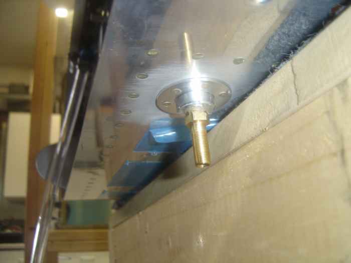 |
Also part of the tank test kit is this
adaptor that attaches in place of the fuel drain. This adaptor has
a tire valve on it so you can pressurize the tank with a compressor or
any hand pump. |
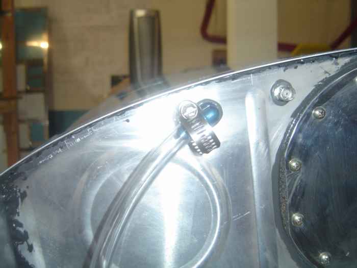 |
I bought 10' poly tubing from home depot
and attached it to the vent line with hose clamp. |
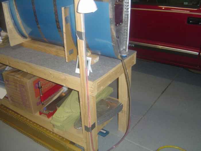 |
The tubing hangs down to the floor and
then runs up another 4 feet. I screwed a 1x2 board to the work
bench and used duct tape to hold the tubing to the board. I then
filled the tubing with colored water until its level was half way
between the floor and the tank. |
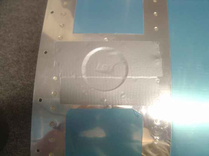 |
Since the fuel cap does not form an air
tight seal, Vans recommends covering it with duct tape. |
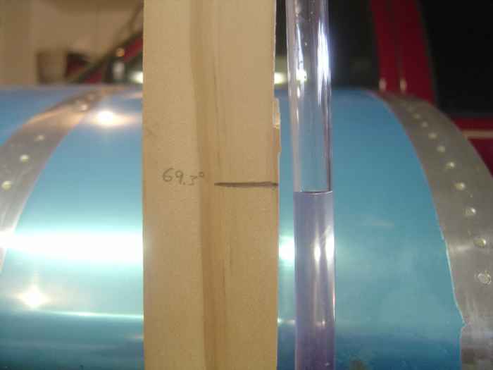 |
Next the tank is pressurized to 1 PSI.
The way of determining 1 PSI is to pressurize the tank until the
distance between the water level on open end and tank side of the tubing
is 2'3" [ this specification comes from Vans in the tank kit ]
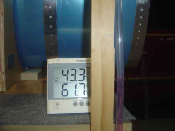
I marked the board at height of the the water level and documented
the temperature, 69.3 F. As the temperature decreases, so will the
water level and vice versa.
Next, I brushed soapy water over all the rivet lines, joints, and
connections. I quickly saw I had a leak coming from under the duct
tape the was covering the fuel cap. I removed the tape and brushed
more soap water over the surface. Yep, air was leaking from the
fuel cap. |
 |
I removed the cap and wrapped it with a
latex glove and then reinserted it. I then covered that with duct
tape and re-pressurized the tank. I tested everything again
with soapy water and could not find any leaks. So far so
good.
I came back out to the shop an hour later and noticed that the water
level had dropped about 2 inches. I also noted that the
temperature dropped about 8.5 degrees. I decided I would let it
sit overnight and check it the next day after things warmed up.... Sure
enough, the next day, when the temperature reached 69.3, the water level
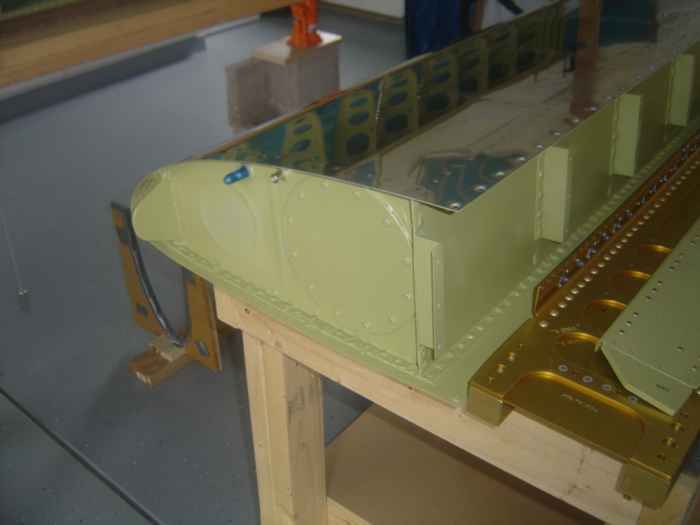
was where it need to be. Wow, it is nice to know this tank
done! |
 |
May 4, 2005:
(1.5 hrs.) In preparation for priming the tank external
facing ribs and baffle, I wiped everything down with MEK. I then
used a Scotchbrite pad and ruffed up the surface. One more good
cleaning with MEK and it was ready for paint. But, before I
do that, I better check for fit on the wing... Yep, fits...
After a simple masking job and quick shot with the
paint gun, the tank was primed and ready for installation. I think
I will let it sit overnight before I install it.
I spent about an hour giving the shop a thorough
cleaning. |
 |
May 5, 2005:
(1.0 hrs.) Did not have much time to work on the plane today, but
I did manage to install the tank on the right wing. Everything
seemed to line up perfect.
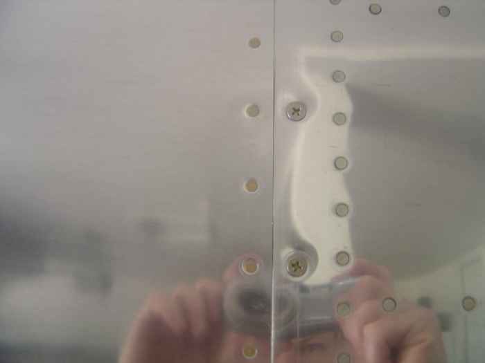
Here is a shot of where the tank and leading edge
join. The picture makes it look like there might be some pillowing
between the screws, but there is not. It is a nice clean fit.
I went ahead and installed all the tank to spar
and leading edge screws. I also torqued all the spare to z-bracket
AN3 bolts. |
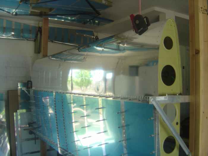 |
Here is a picture of the right wing with
the tank and leading edge installed. My plan is to rivet on the
top skins next weekend. |