 |
May 2 - 18, 2008:
(10.0 hrs.)
It has been a while since I have made any entries on my progress.
That is mainly due to the fact that I have only had small bits of time
here and there to work on the plane and I did not feel like on there own
these events were worth my while to post.
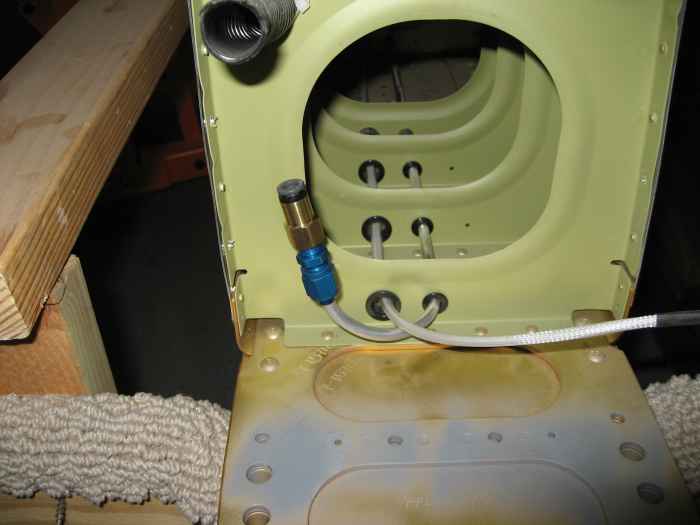
I decided to complete the plumbing for my pitot line. Here I
have cut and terminated my 1/4" aluminum pitot line in the left wing
with a special adapter I got from
SafeAir1. This adapter will transition from 1/4" aluminum line
to the SafeAir1 green nylon pitot line which I decided to run through
the fuselage and up to the panel.
|
 |
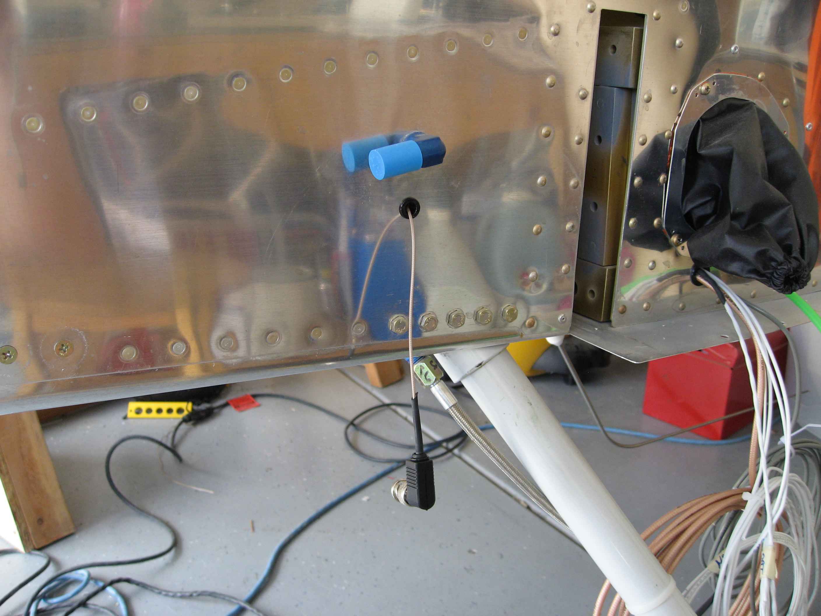
I drilled a hole in the left fuselage wing
root area and inserted a 1/4" plastic grommet for routing the pitot
line. |
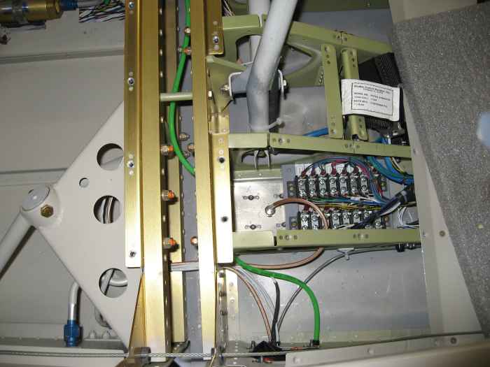 |
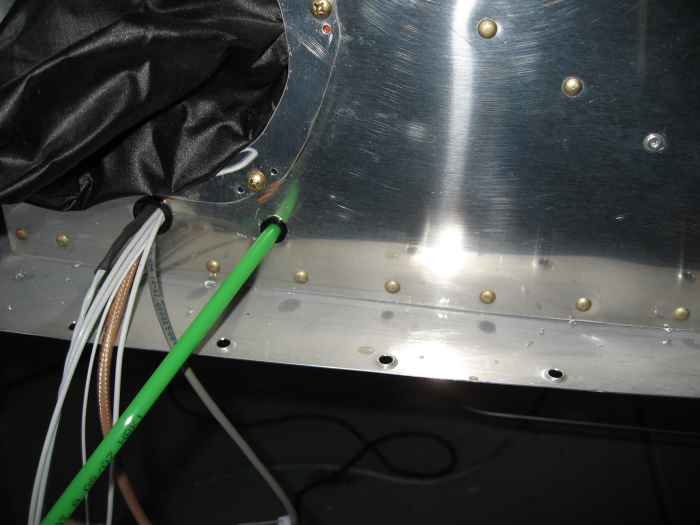
On the inside of the fuselage, after much
back-and-forth thinking on how I wanted to route the pitot line up to
the panel, I decided to take a route through the center tunnel. I
have all my other wiring and plumbing lines taking that route, so I
decided the pitot line should not be treated any differently. Here you
can see the green pitot line coming into the fuselage from the left wing
root area, it then proceeds through the aft center section spar webbing
via a new hole I drill in the second seat rib bay (takes a 1/4 grommet).
From there it traverses between the spar center section where it then
routes through the front spar center section webbing using an existing
electrical run hole. It then takes a normal path up under the
center tunnel cover, up the firewall, and behind the sub-panel. |
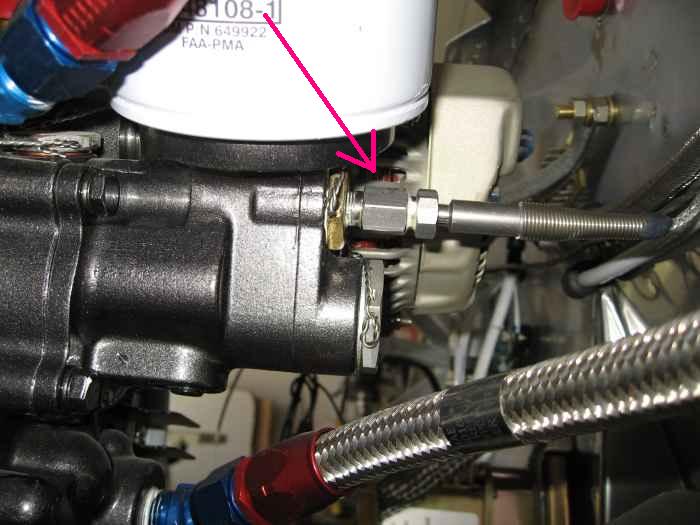 |
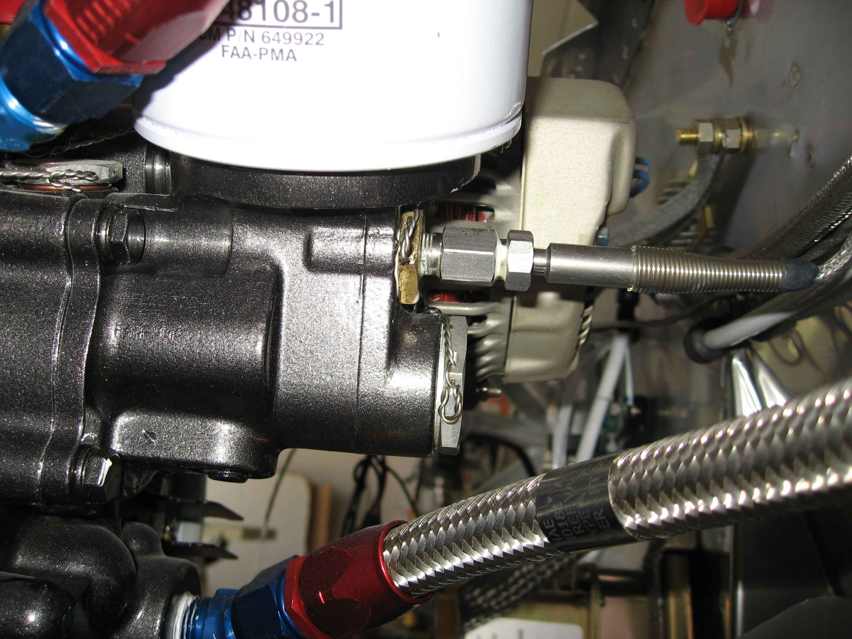
I installed the oil temperature probe and
wired it into the FADEC system serial bus controller harness.
I seem to remember reading somewhere that this probe should use a
crush washer under the reducer fitting or else you will have a small oil
leak. I ordered one from Aircraft Spruce and will install it
later. This think is in a really difficult location to reach with
a wrench, so I am not looking forward to taking this off and on again. |
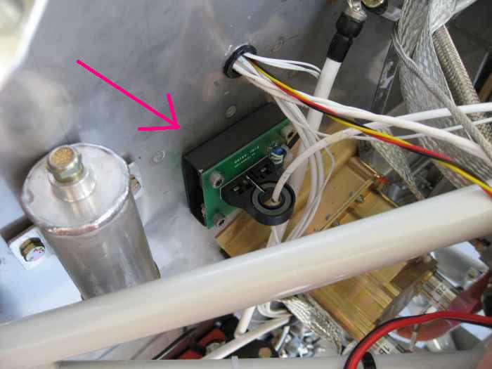 |
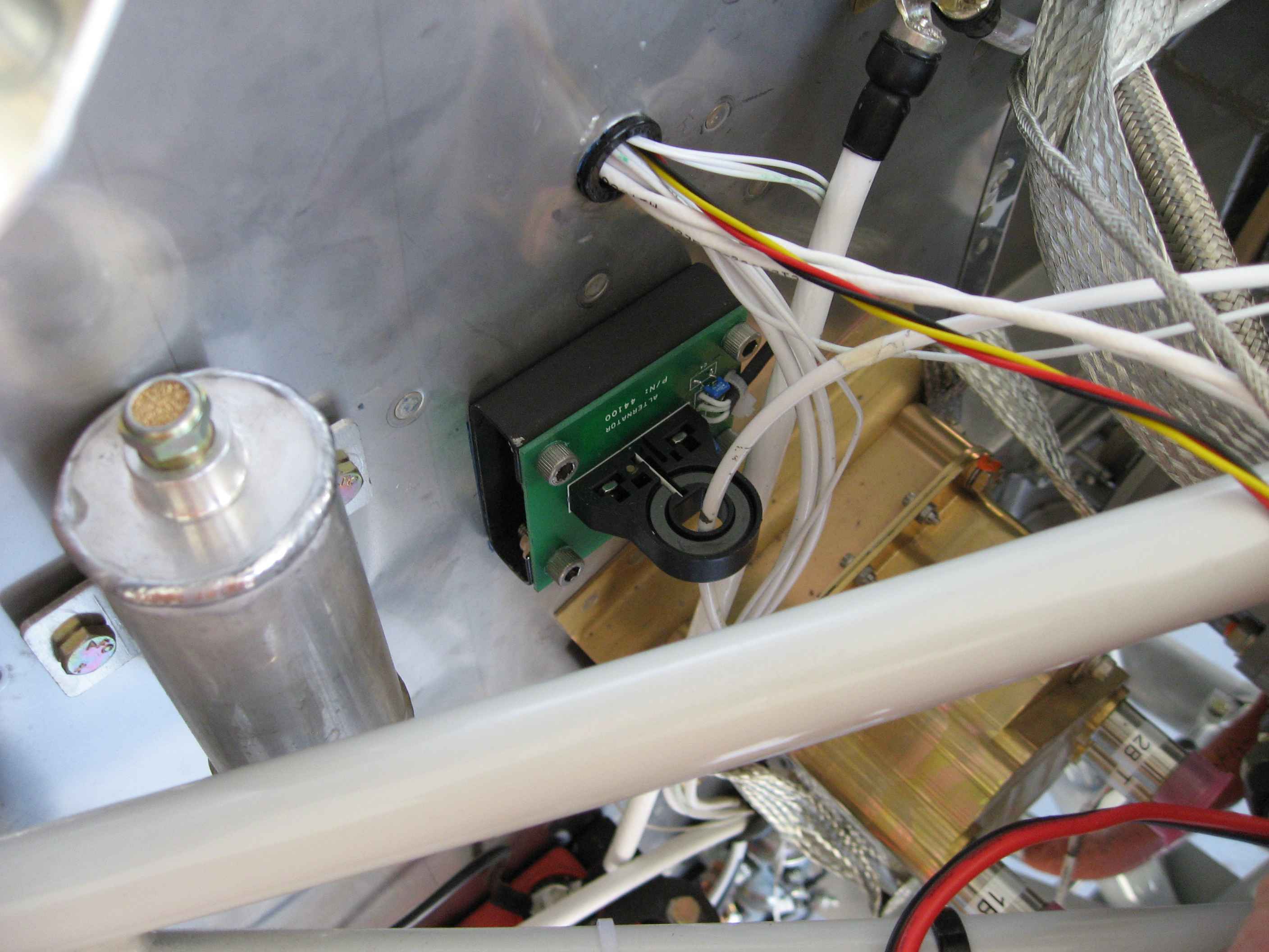
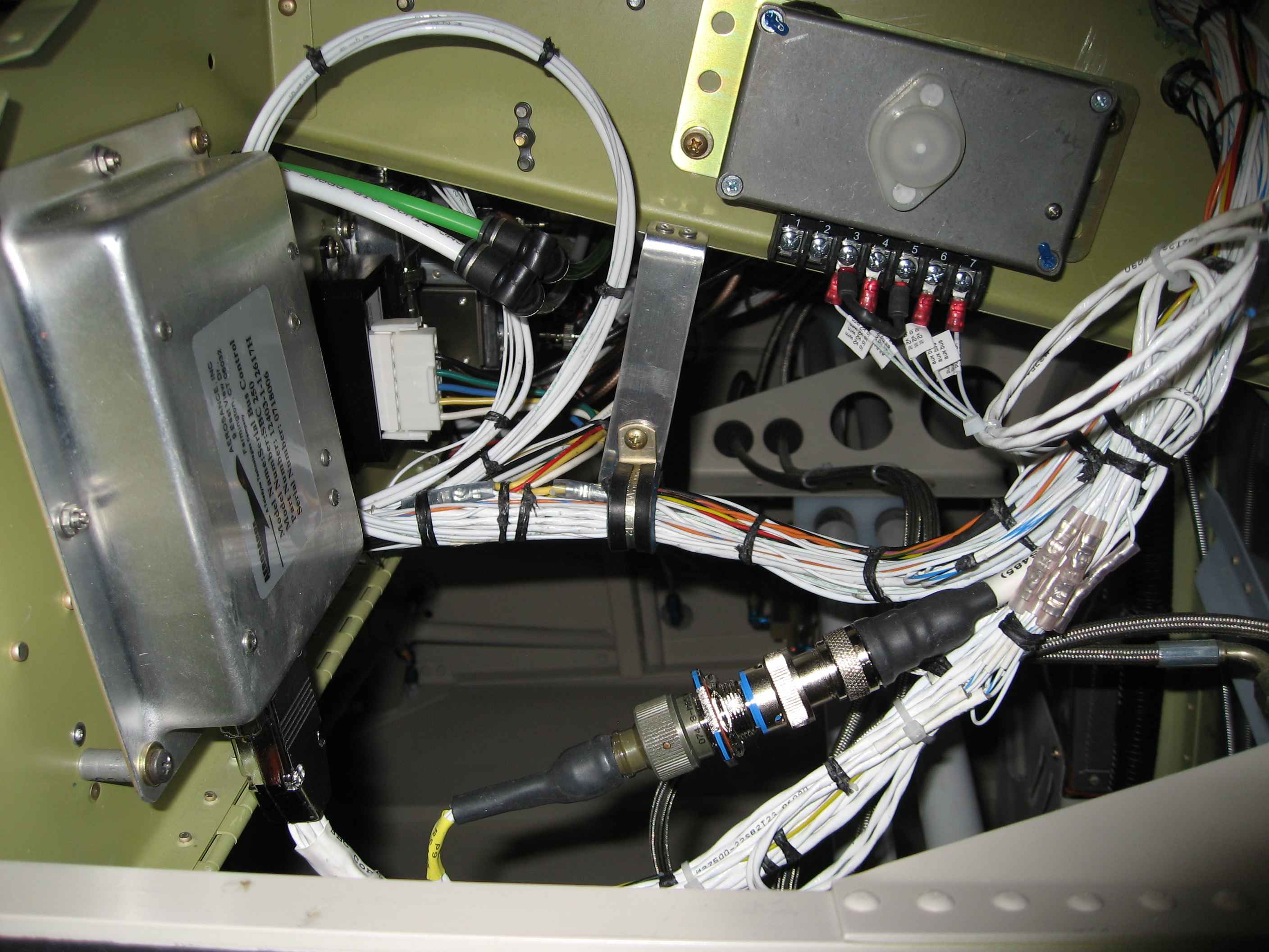
I fabricated a bracket to mount the Hall
Effect sensor to the firewall. The sensor setup has a bare circuit
board on the backside that needs to mounted so that it does not touch
metal. My bracket, although hard to see in this picture,
essentially looks like two U channels with one flange riveted to the
firewall and the other flange configured with nut-plates to except
screws through the circuit board.
The Hall Effect sensor has the wire running from the auxiliary
alternator to the battery running though it. Its purpose is
to measure the charge rate of the battery. If you see no charge,
then it is a good sign your alternator is out. |
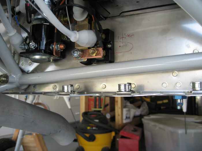 |
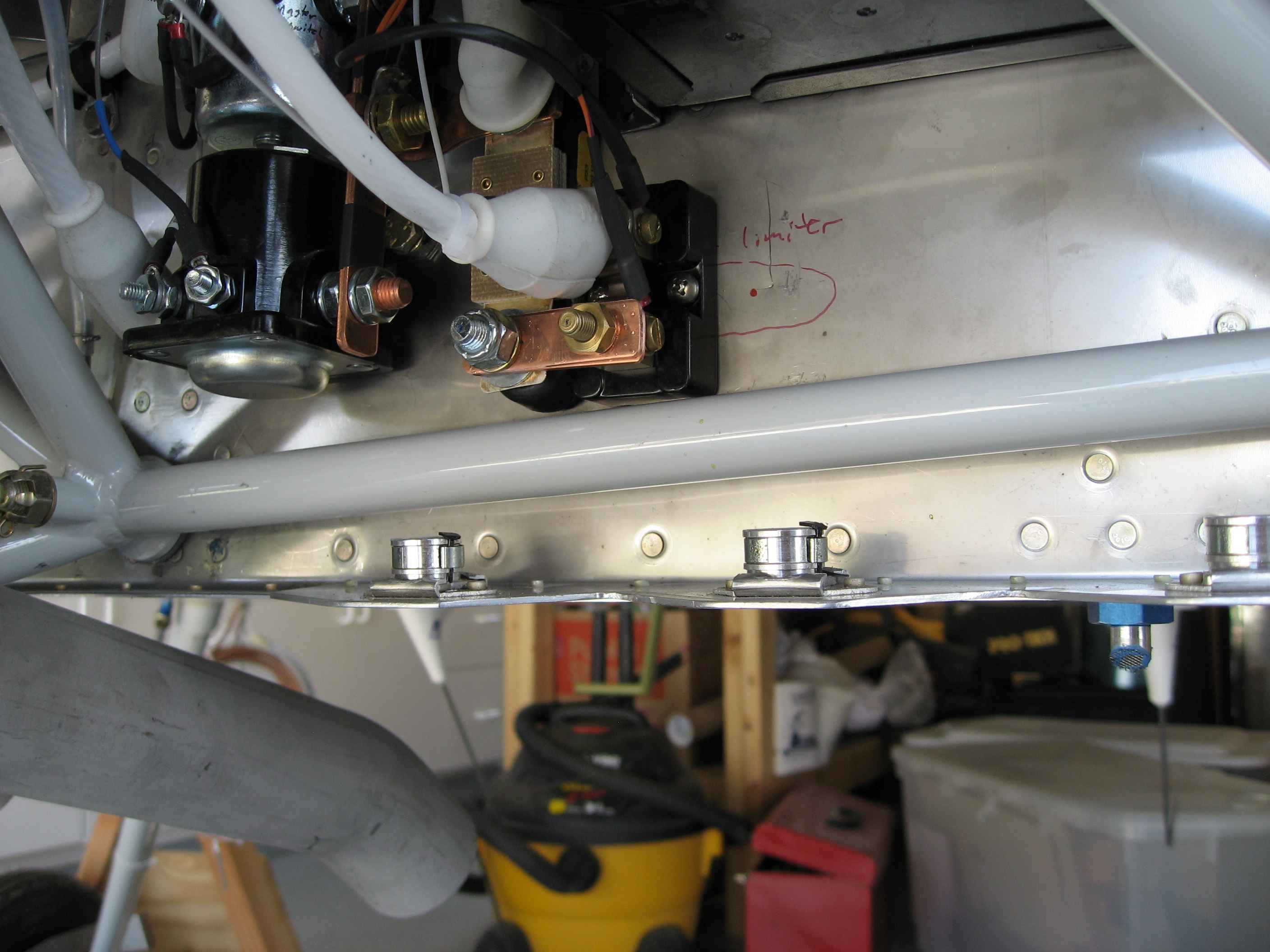
Next, I installed the amp shunt to monitor
the charge rate of the main alternator. It does the same thing as
the Hall Effect sensor. Why use a different charge monitoring
technique for the two alternators? I have know idea, other than
that is how Advance Flight Systems (my EFIS and Engine Monitor vendor)
wants it done. |
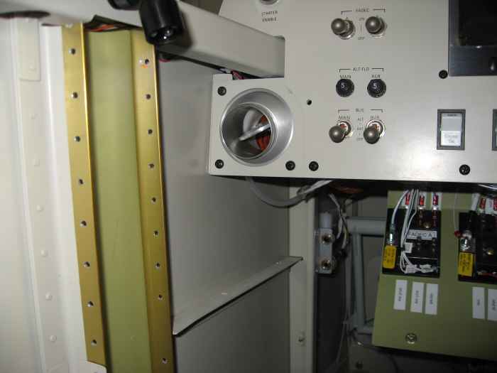 |
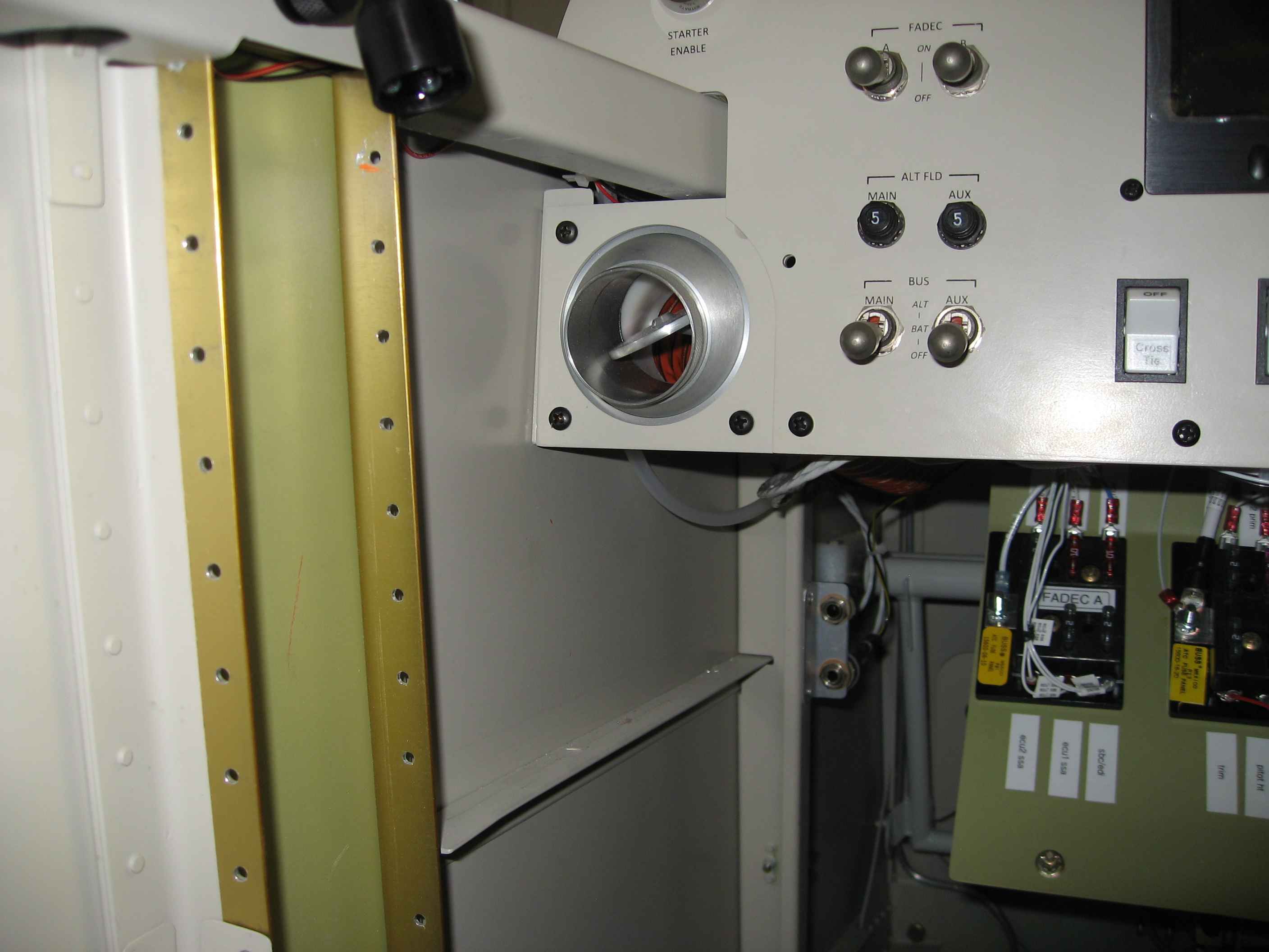
Finally got around to installing the fresh
air vents.
Here is the pilot side vent |
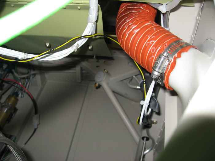 |
I also installed the SCAT tubing to
connect the fresh air vents with the outside facing NACA vents. I
am not sure if this orange SCAT tubing that came with the kit is only
for the hooking up the heater vent box to the heat muff, or can also be
used for the fresh air vent... Oh well, if I am short SCAT tubing for
the heater vent I can always order more. |
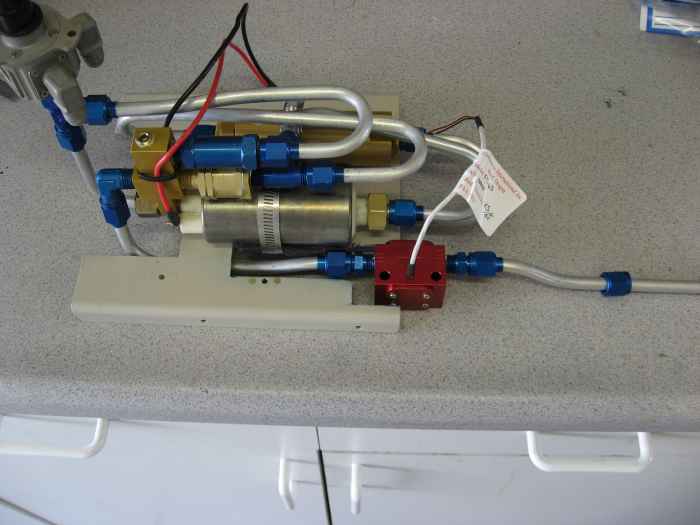 |
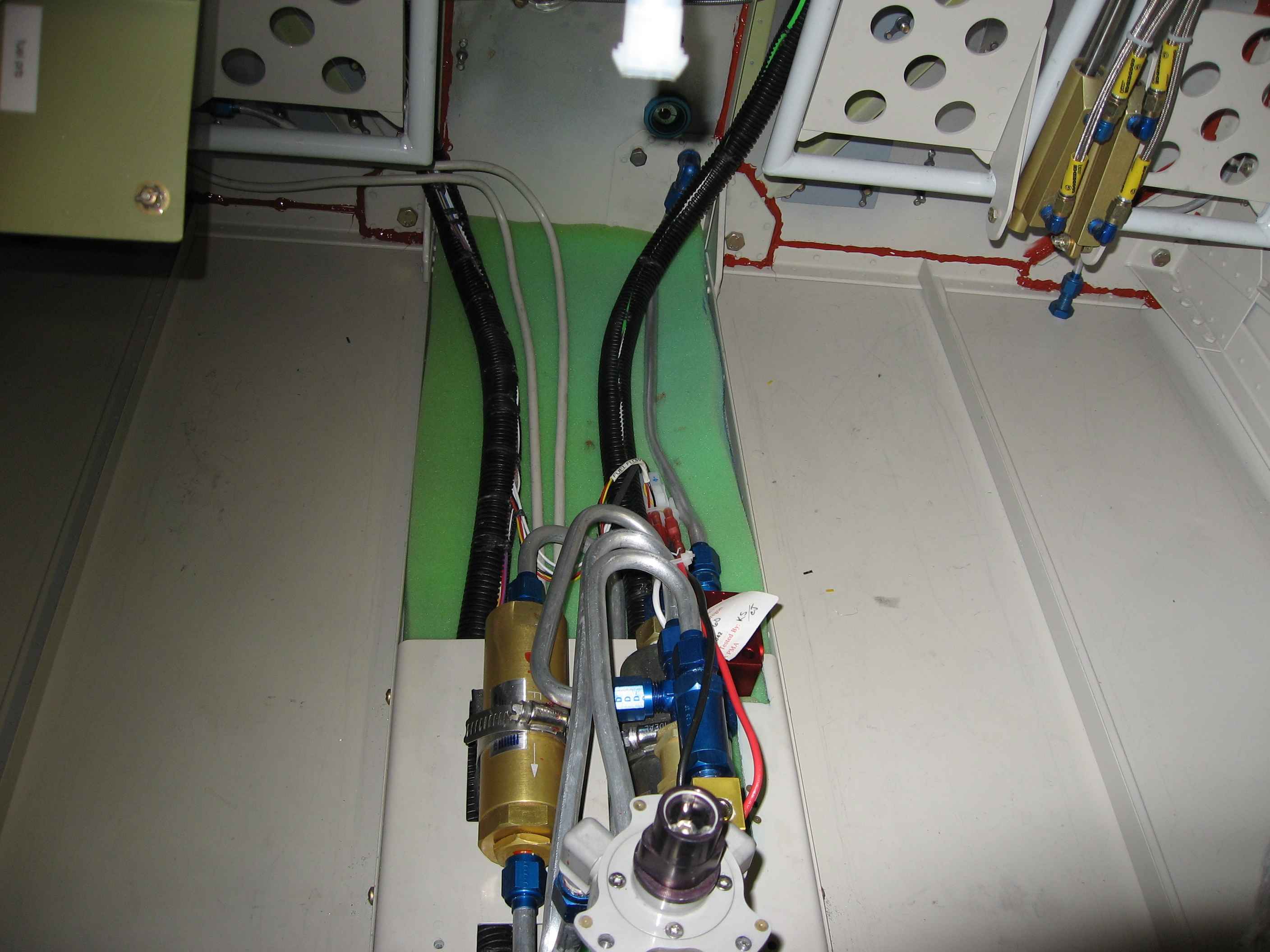
One of the last bits of systems work is to
install the fuel flow sender. There is much debate on the best
location where to install this, each with its pros and cons... I have
settled on putting it inside the cabin right after the fuel pump.
I pulled out the fuel boost pump assembly from the cabin, trimmed the
mount plate back a bit for the 'red cube', and cut/bent/fit the 3/8"
fuel outlet line to the fuel sender. |
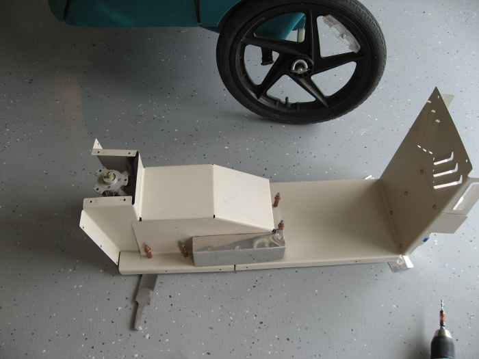 |
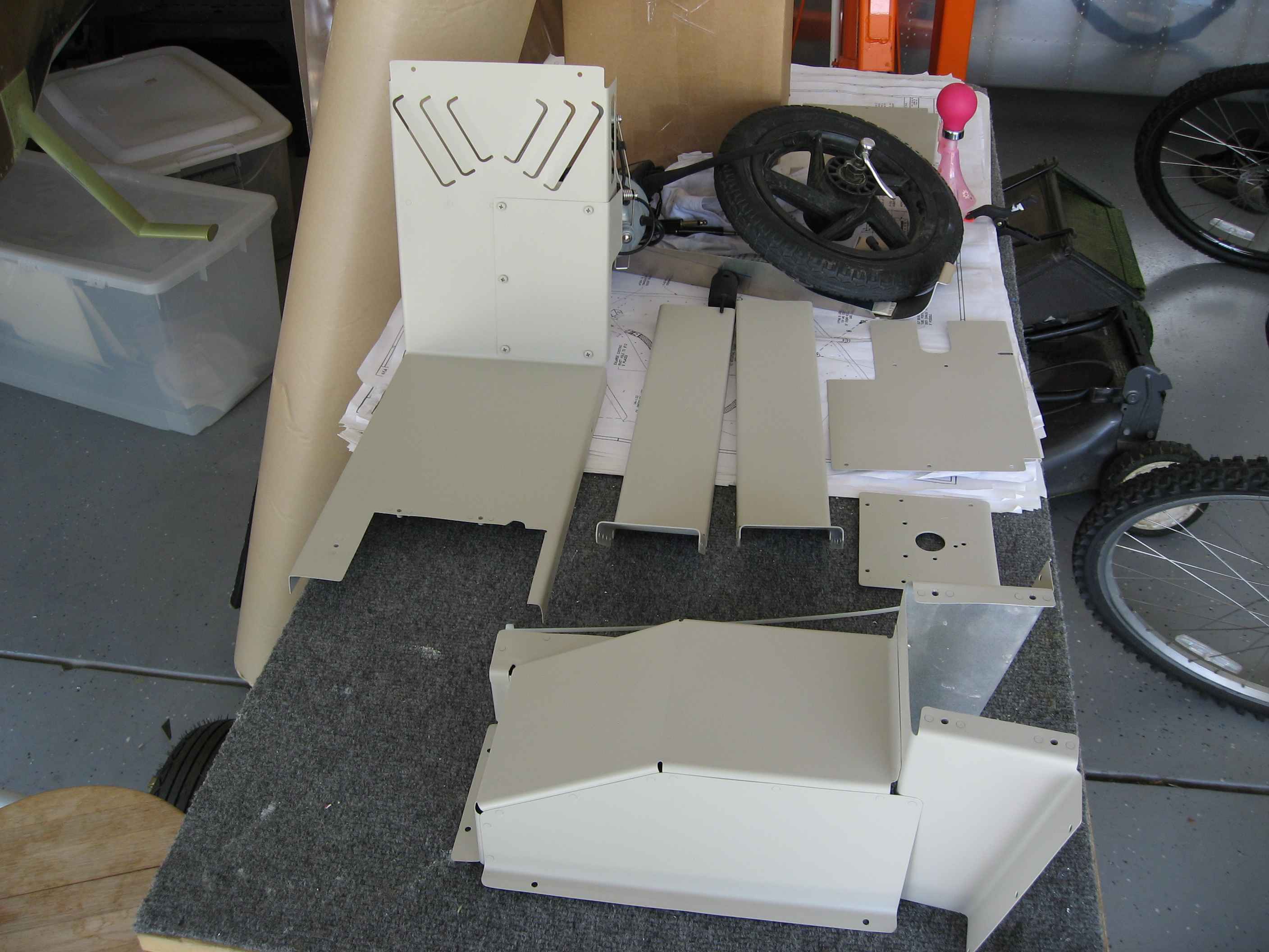
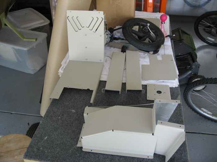
I was hoping to avoid modifying the fuel
pump cover plate to accommodate the fuel sender, but there was just no
other way. Here you can see the additional bump-out (basically a
small box) that needed to be fabricated and fitted to the cover.
This will get a coat of paint before I put it back in the cabin. |
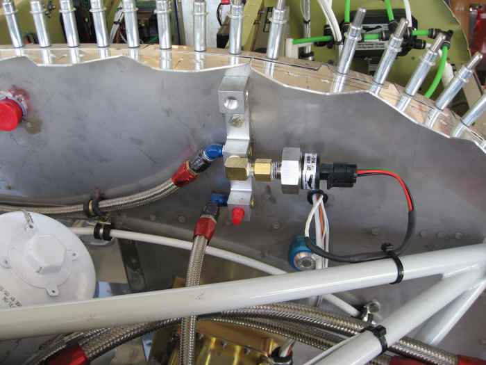 |
May 23 - 25, 2008:
(10.0 hrs.)
Continued with some miscellaneous items.
Here I have installed the oil pressure sensor for my FADEC system. |
 |
I rerouted my capacitive fuel level sender
wires. I had originally routed these so that they were exiting the
fuselage with all the other wires that run out to the wings. I
then remembered that the fuel sender connectors on the wings were in
front of the main spars, so I made these holes below the fuel line
bulkhead fittings and rerouted the sender wires. |
 |
We had a some nice weather over Memorial
weekend so I shot another coat of paint on the center tunnel covers. |
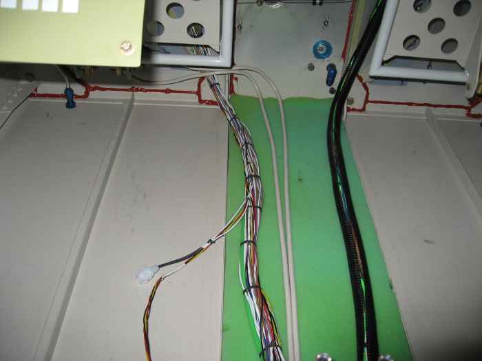 |
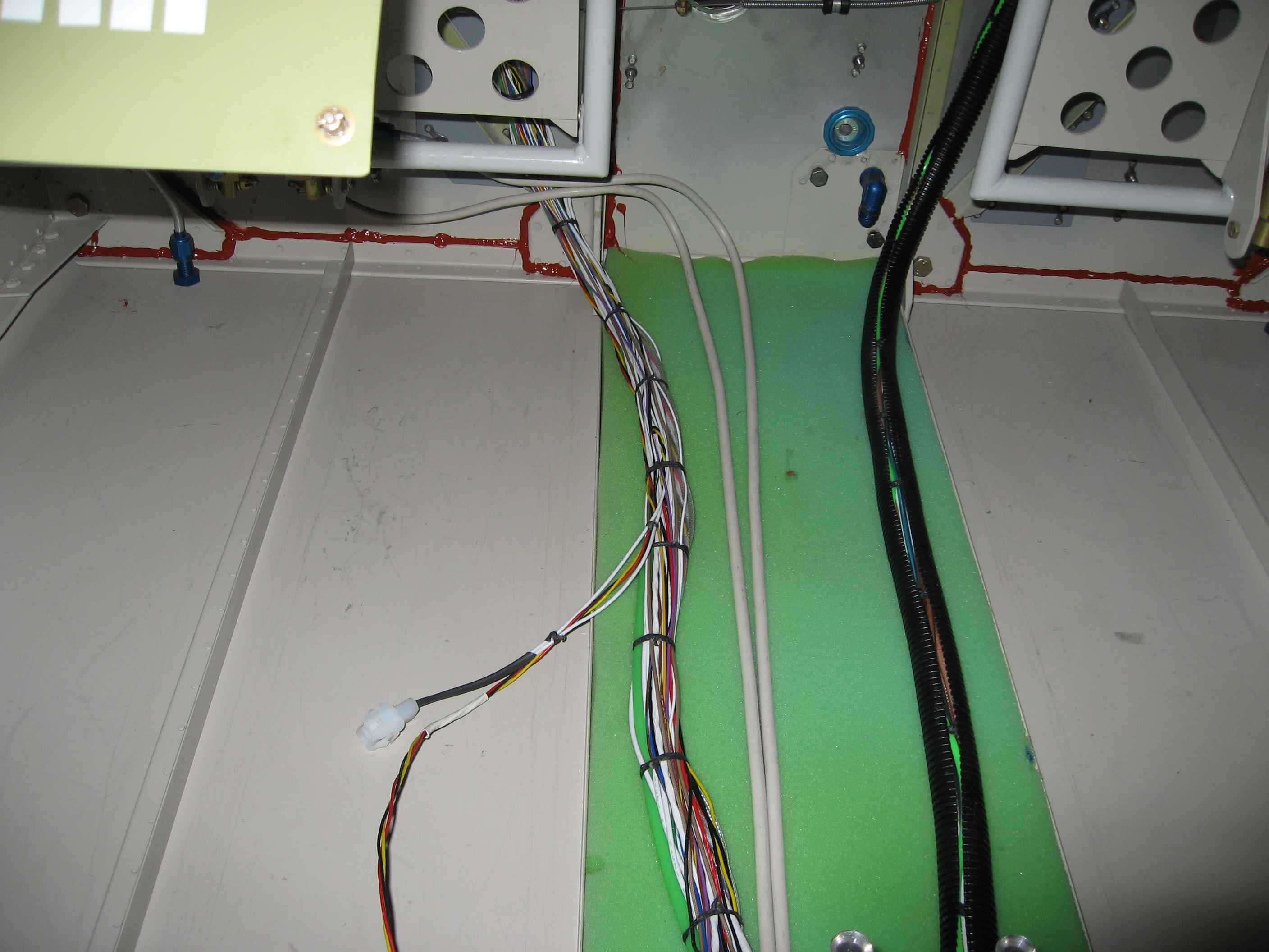
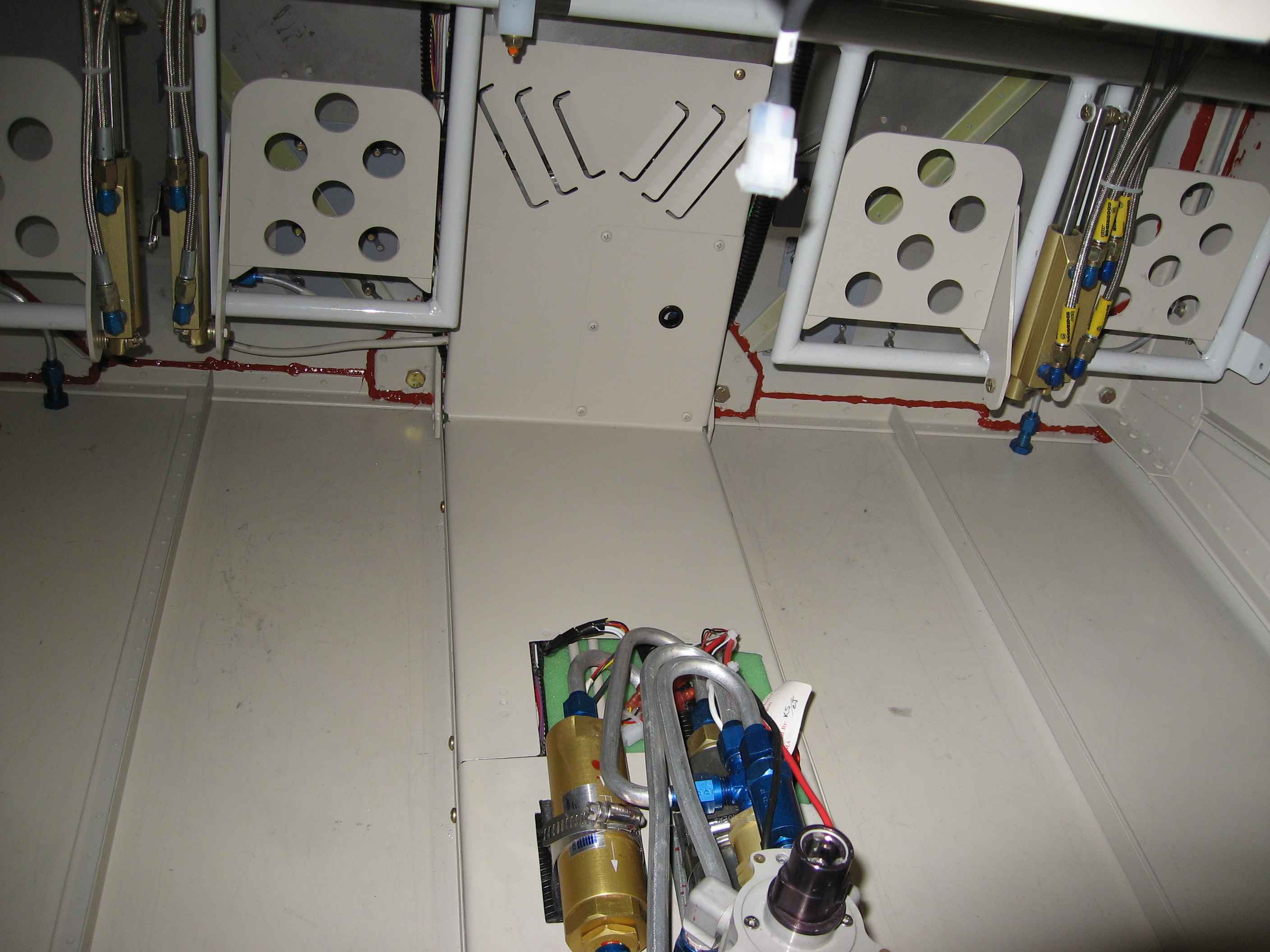
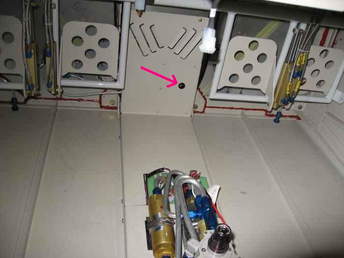
I laced up the wire bundles that run under
the center tunnel. I also slit some black conduit open and used
that to cover the bundles. This probably was not necessary, but I
was a bit concerned about chaffing of the wires once the center tunnel
cover was installed. The green stuff is some foam that will keep
the wires bundles, oil and fuel lines off the bottom skins. |
 |
Next, I reinstalled the fuel boost pump |
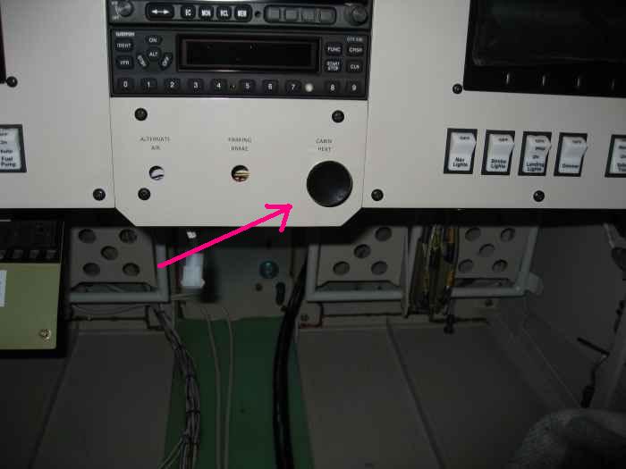 |
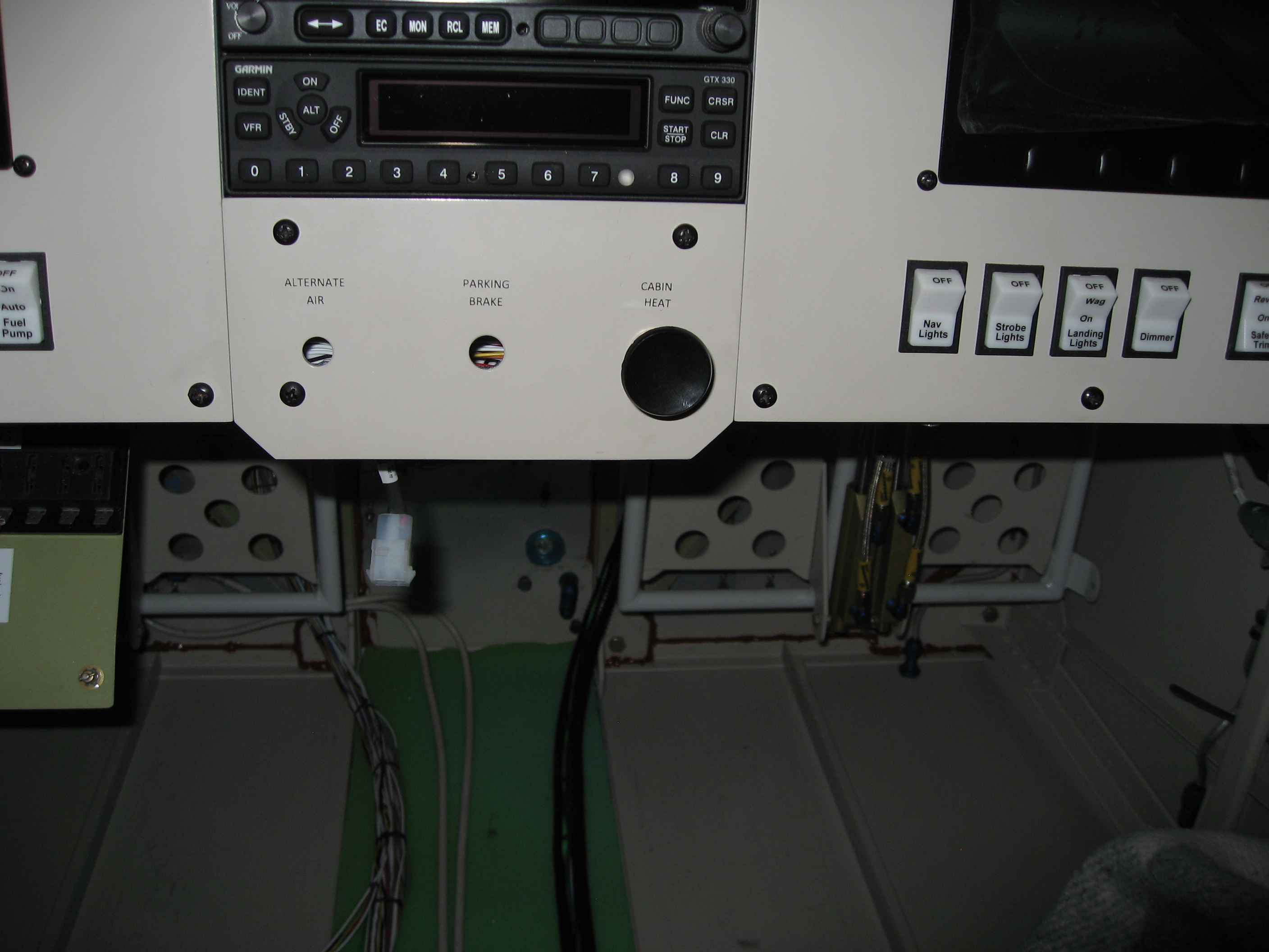
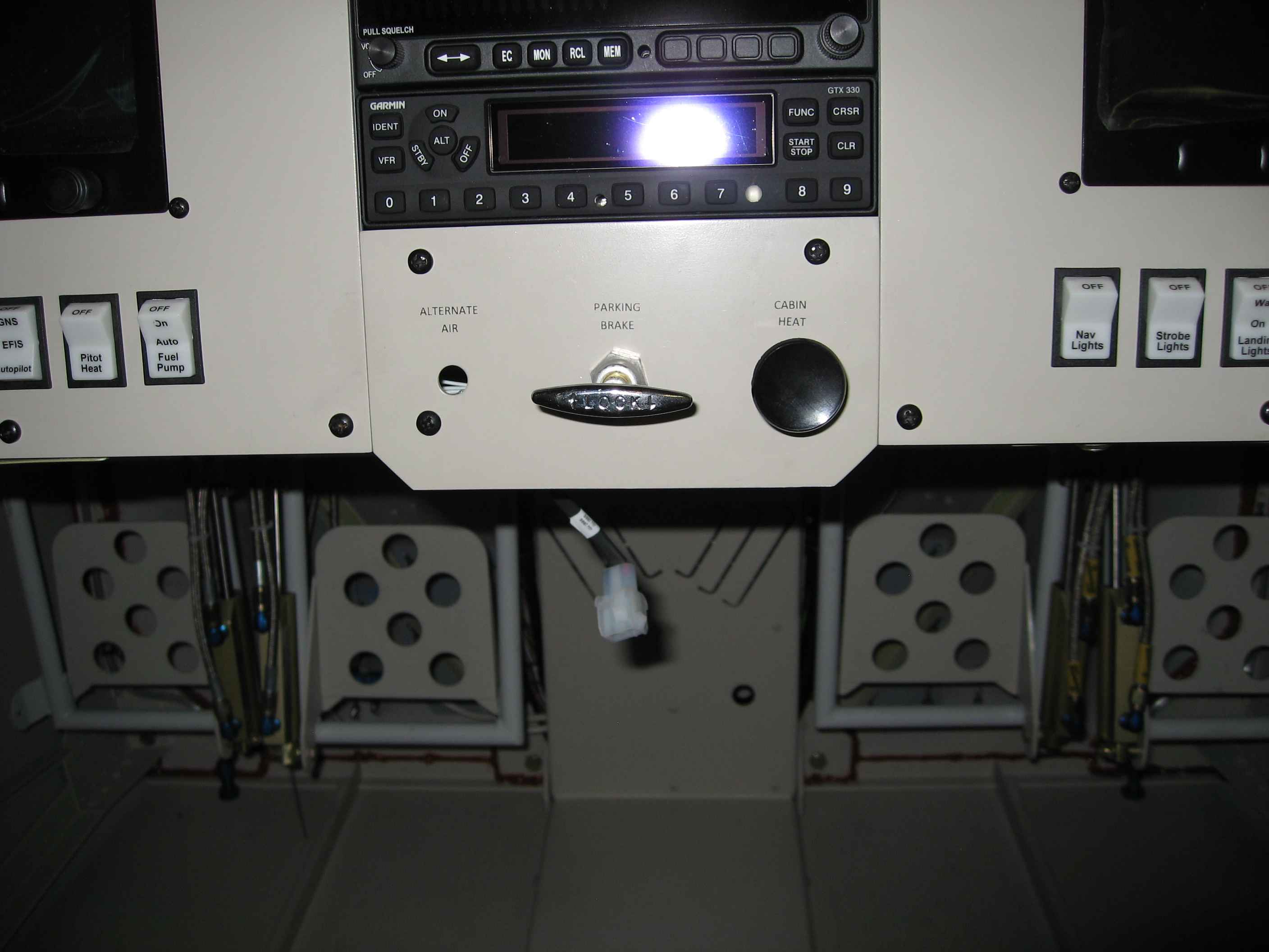
I rigged up the cabin heat cable.
Shown is the pull knob for the cabin heat. I had to shorten the
cable quite a bit and found that the ScotchBrite wheel on the bench
grinder worked great for cutting the steel outer sheathing. |
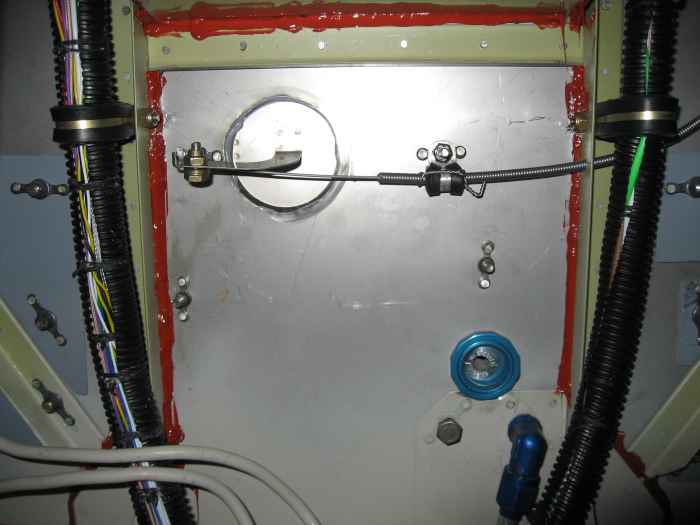 |
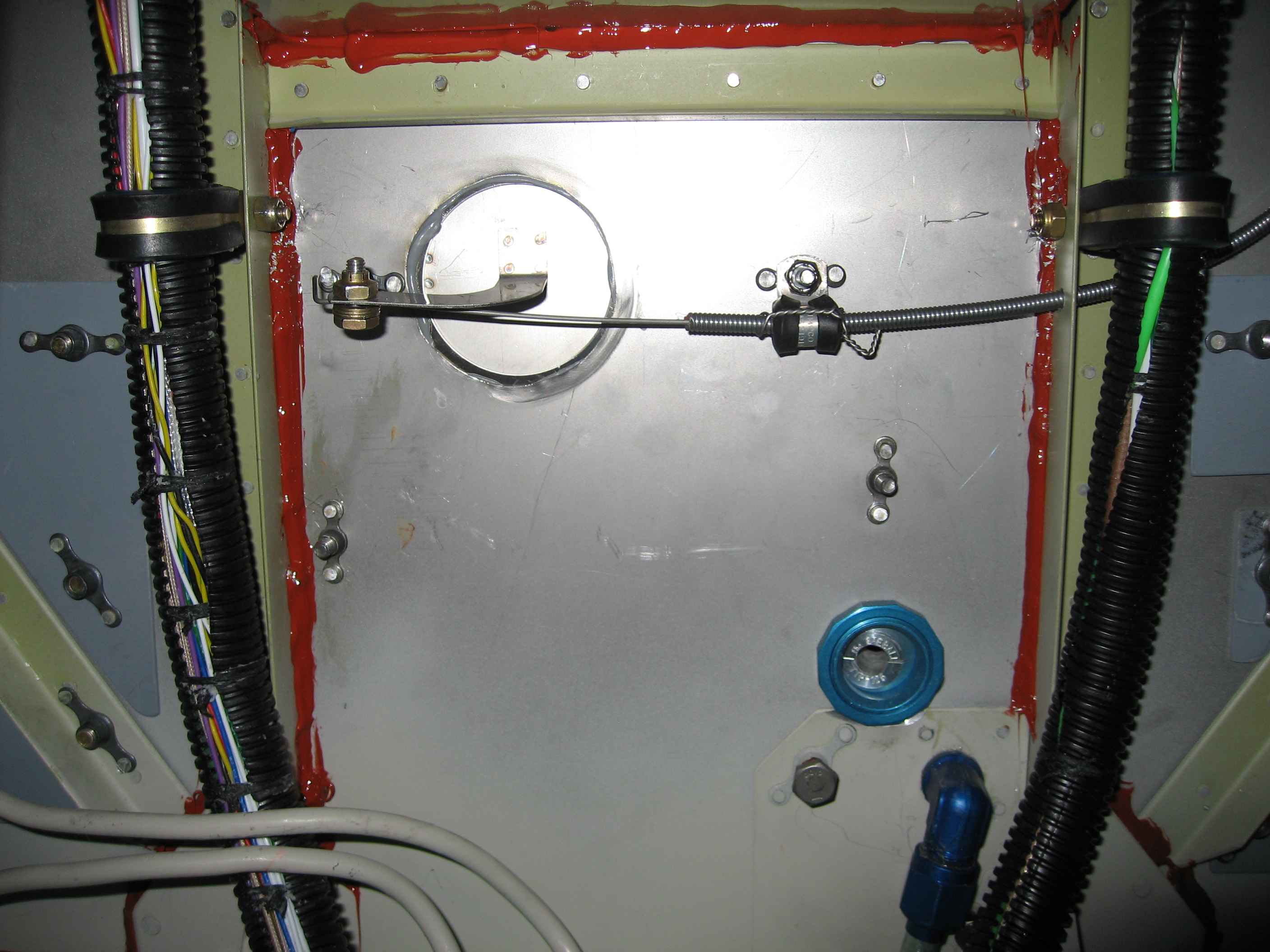
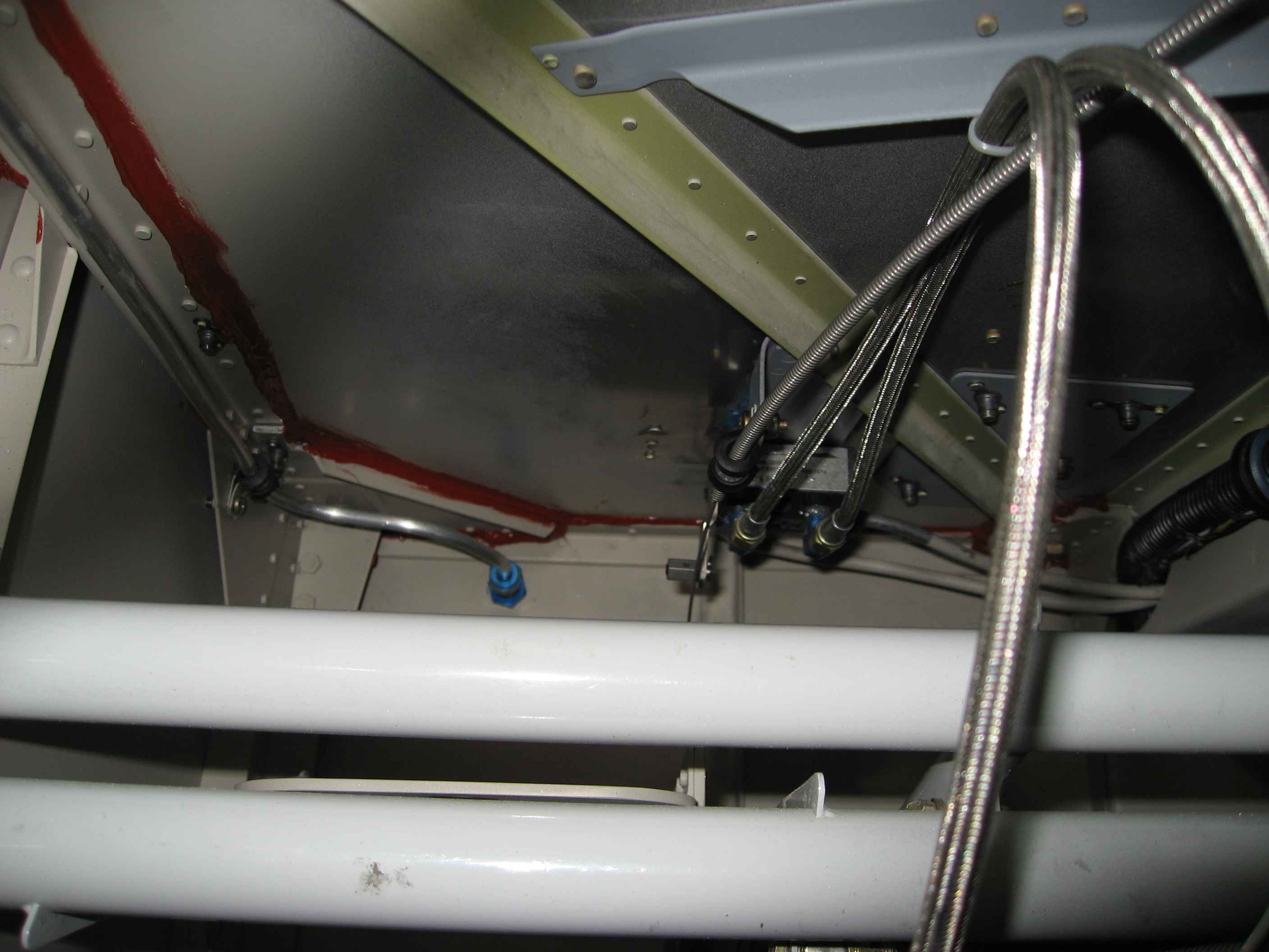
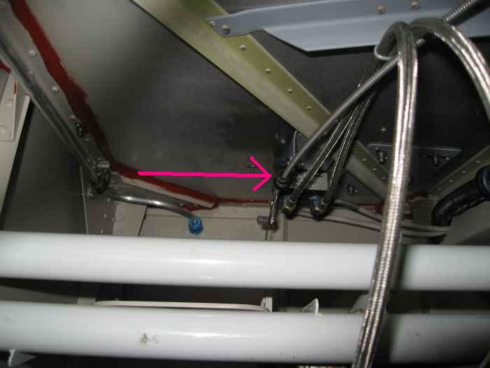
Here is the other end of the cabin heat
cable connected to the heater valve (more like a flapper assembly).
The cable runs through a hole I drilled in one of the firewall
stiffeners and then is held in place by an Adel clamp. The cable
is safety wired in place around the Adel clamp to keep things secured.
Another thing I did is put a bunch of Hi Temp RTV on the firewall joints
(the red stuff in the picture). I thought this might help seal
things up and keep out the carbon monoxide.
Also, I installed another set of large Adel clamps to further secure
the wire bundles running up the firewall |
 |
I then put installed the center tunnel
cover. I drilled a hole and used a grommet where the throttle
cable will pass thru. |
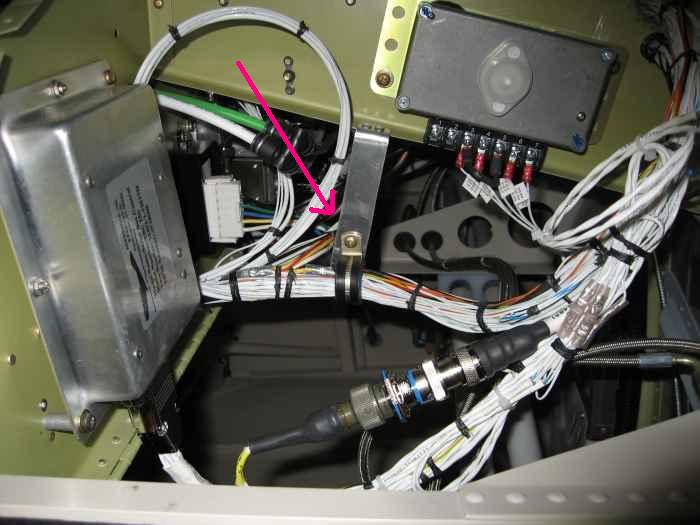 |
I had been a little worried about the
weight of the large wire bundles behind the sub-panel causing fatigue in
the wires over time... So, I came up with an idea to make some aluminum
hangers from the sub-panel rib that have Adel clamps on their ends to
hold the wires in place. I made one of these for the wire bundles
on both the left and right side. |
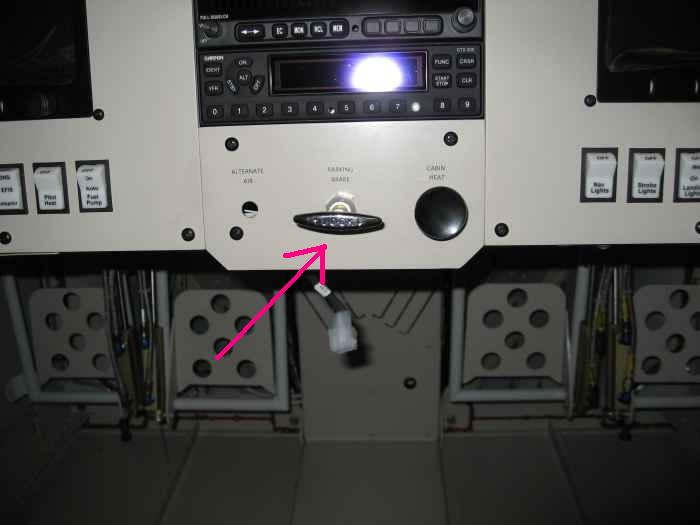 |
Next, I installed the parking break cable.
Here is the knob end. |
 |
It's a bit difficult to see in this
picture, but this is the end of the parking break cable where I have it
secured in an Adel clamp attached to the parking break mounting point.
I still need to rig the end of the cable and safety wire it. |