
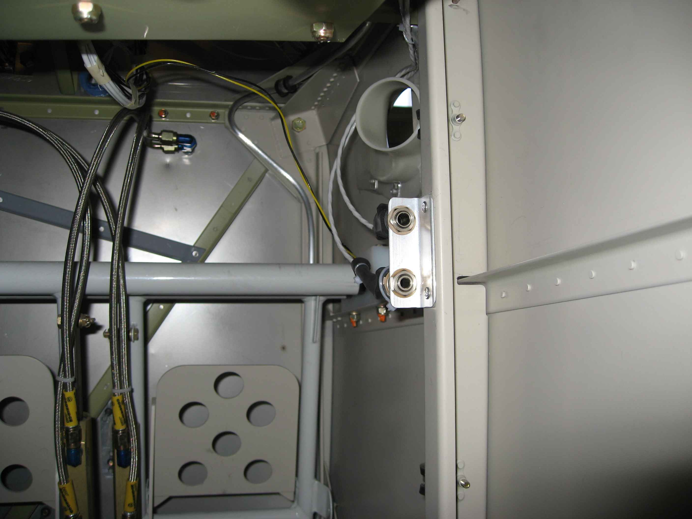
Did some miscellaneous wiring work on the plane. Here I have installed a Molex connector on the fuel pump power lines.
BTW.. the shielded cable for my tail light strobe also includes the wires for the rear Nav light.
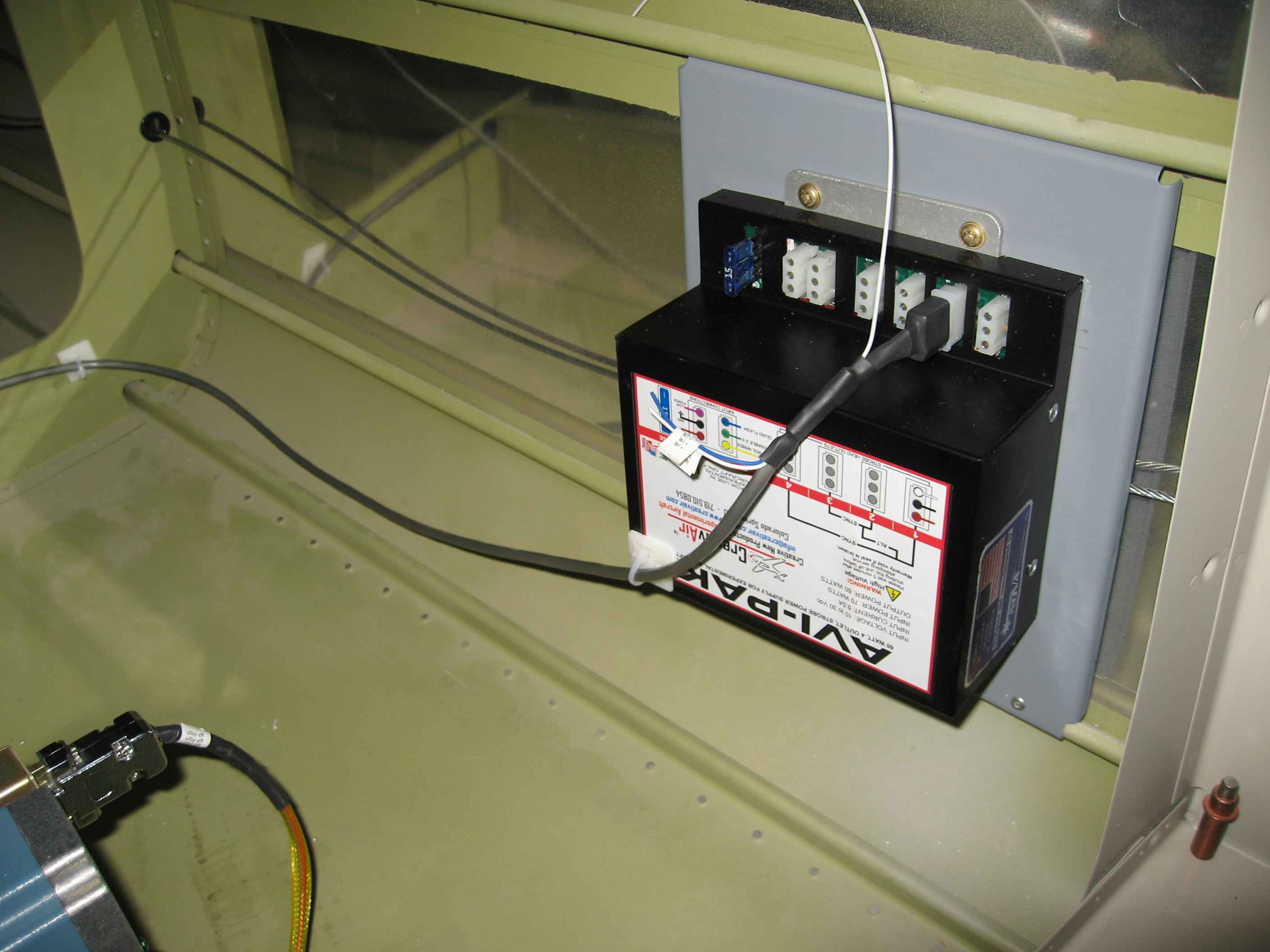
While I was at it, I also started running the power and ground wires for the strobe power pack.
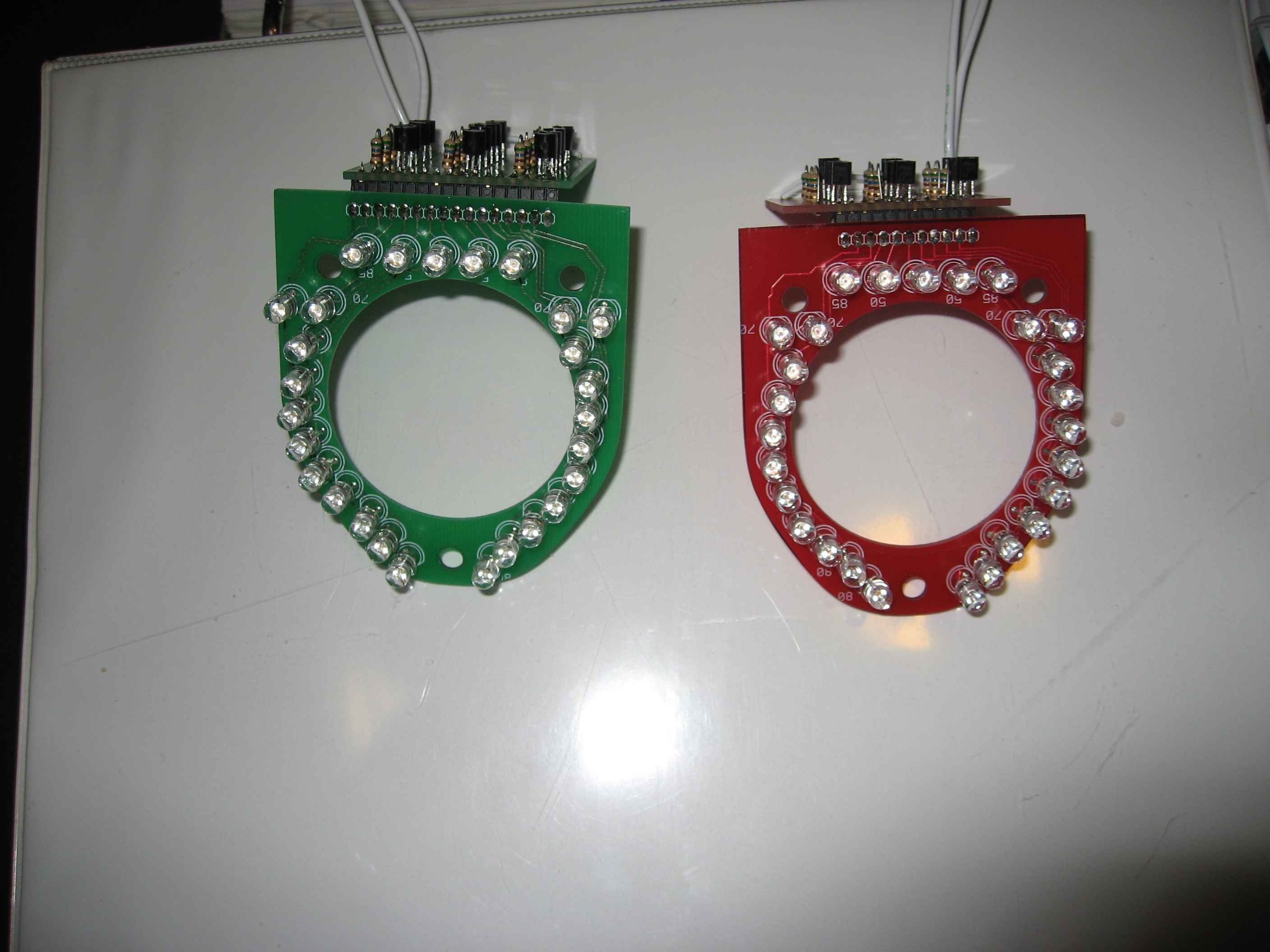
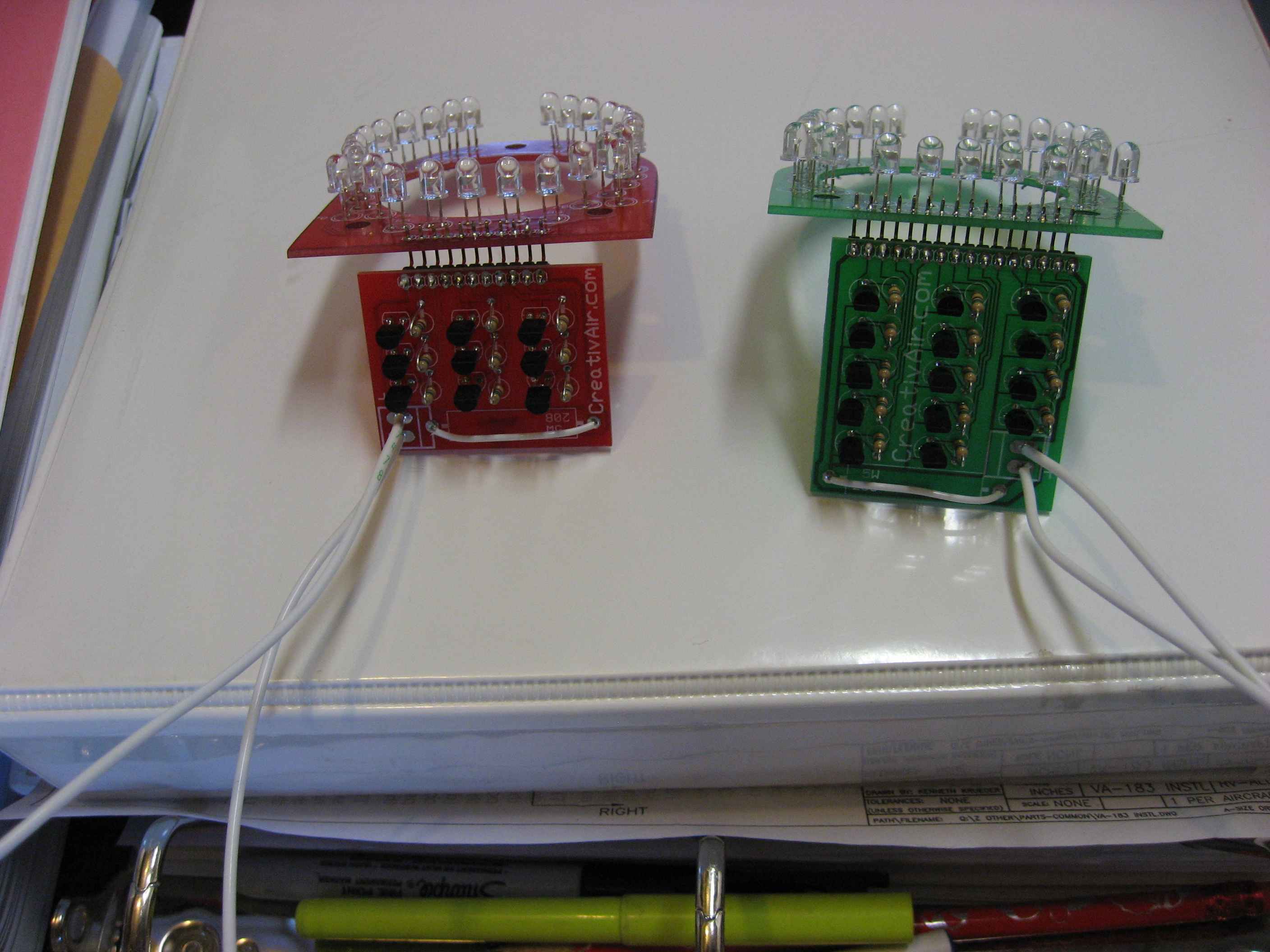
Its a 3 day weekend (Presidents Day) and I was hoping to make some great progress on the plane, but I felt like I was coming down with something and did not want to risk working in the cold garage. I had to work on something! So, I decided to build my LED navigation lights. I bought these in a kit from Creativair. I think having LEDs is the way to go. They last practically forever and they draw very little in the way of amps. You can by these units pre-built, but I wanted them in kit form because I need the LEDs to sit a bit taller. I am planning on mounting these behind either mirrored acrylic or polished aluminum.
Wiring, wiring, and wiring.
I have not been as good lately at logging what I have worked on... The end is in sight, I am just trying to plow ahead.
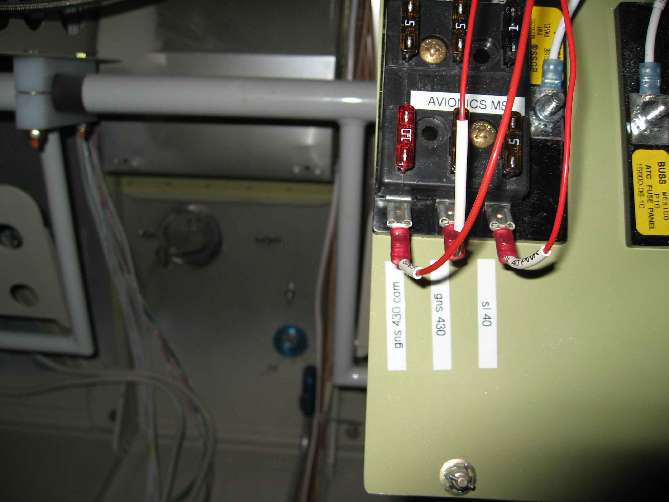
One thing I did was add an Avionics Master switch to my panel. Originally, I had not planned for this but then decided it would be an item of convenience for controlling the power to all the radios while maintaining there set volumes. Because of this addition, I needed to modify my power bus layout. I converted the always hot bus to an avionics bus and switched it off the auxiliary bus. As it turns out, I don't really need the always hot bus for the equipment I have installed in my plane, so this should work nicely.
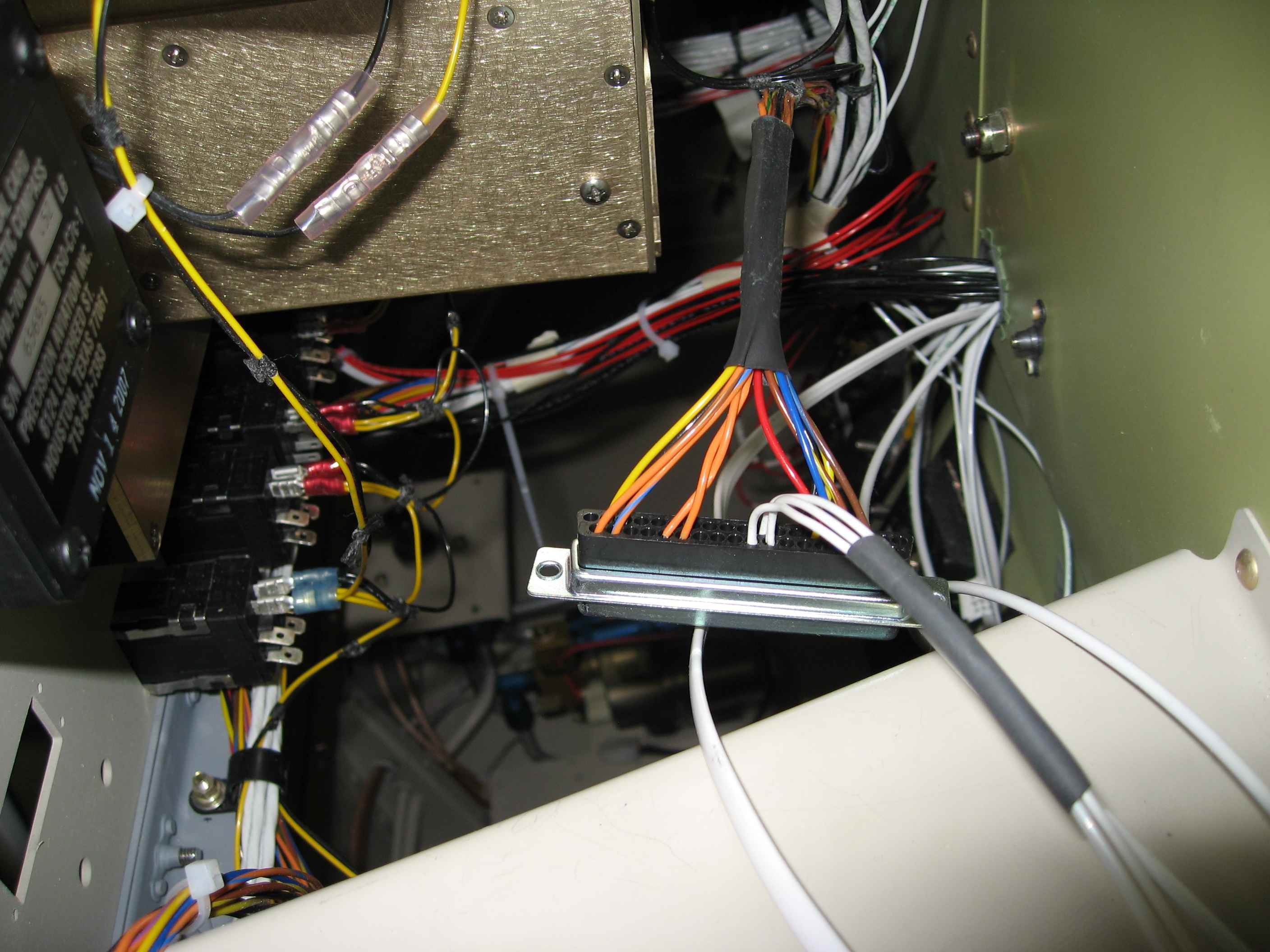
Here you can see the large DB connector hanging loose and the three additional wires that I added.
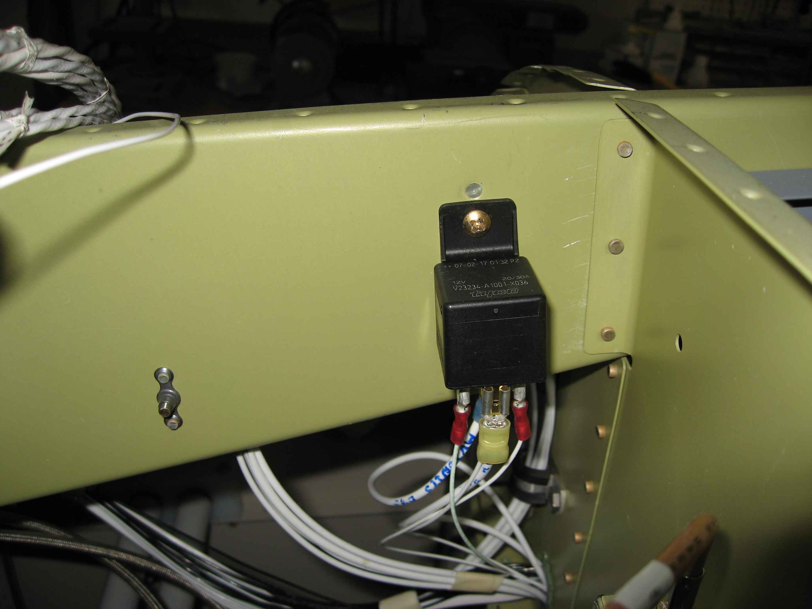
I also had to add a wire to the EFIS and Engine data harnesses for the backup power. This allows each system to monitor the secondary battery voltage and use it as backup if the primary fails.
I may still make a cover for these connectors, but I have not yet decided if one is needed. These connections are pretty far forward and the under panel... out of sight, and out of the way.
Here is one of the mounts I fabricated and installed. The magnetometer that sits in this mount must be +/- 0.2 degrees in both X & Y directions of how the EFIS system sits.
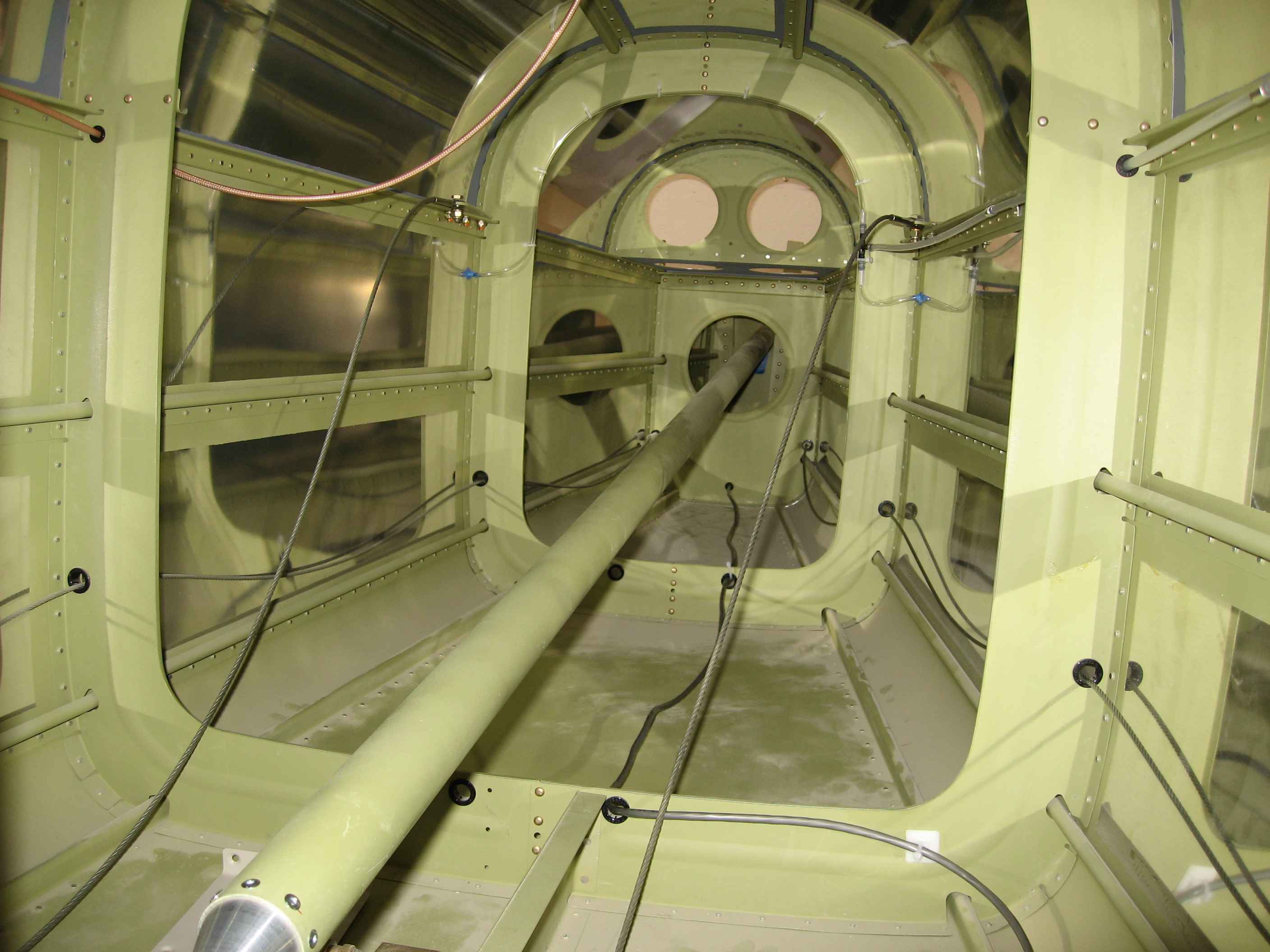
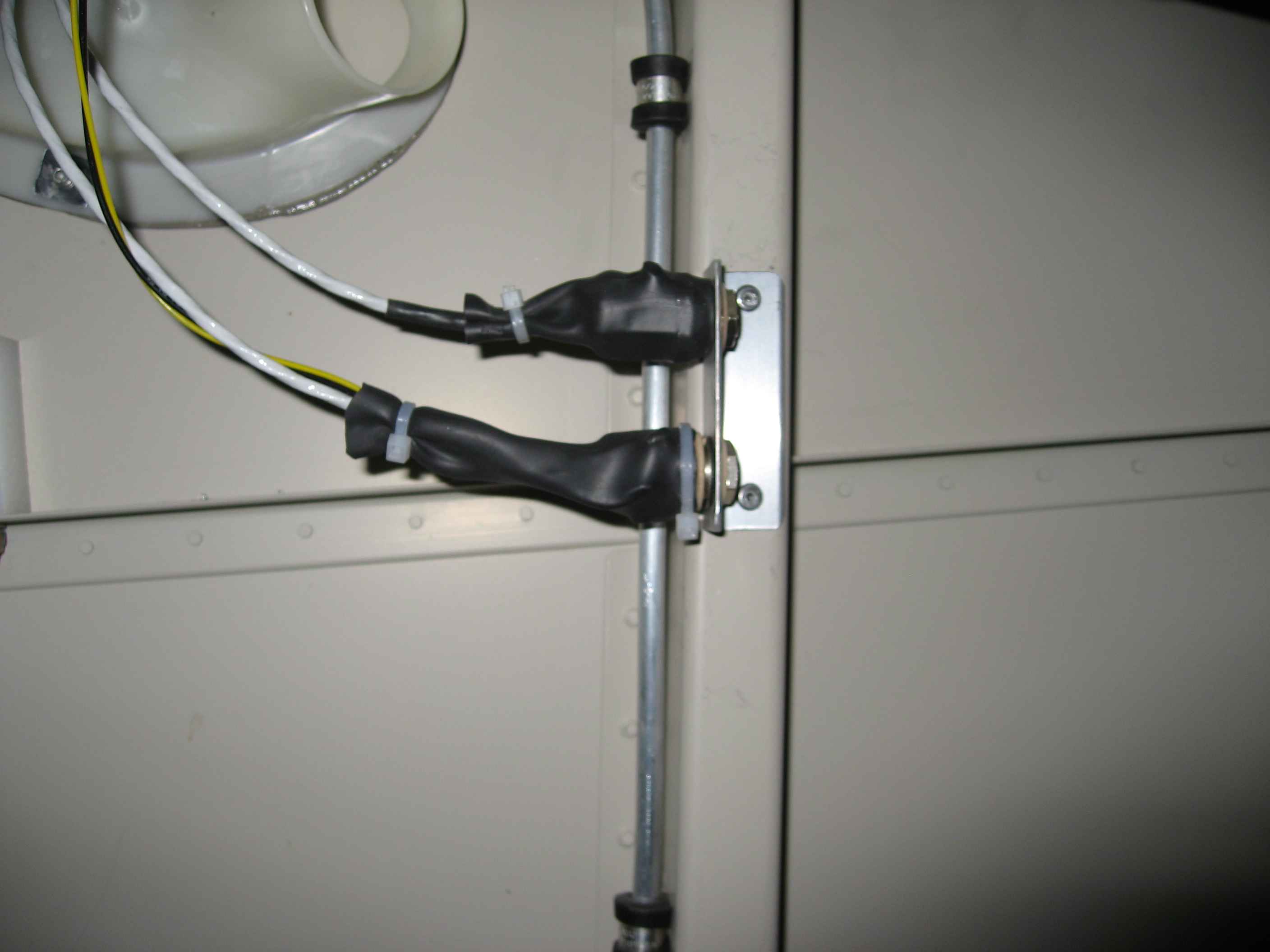
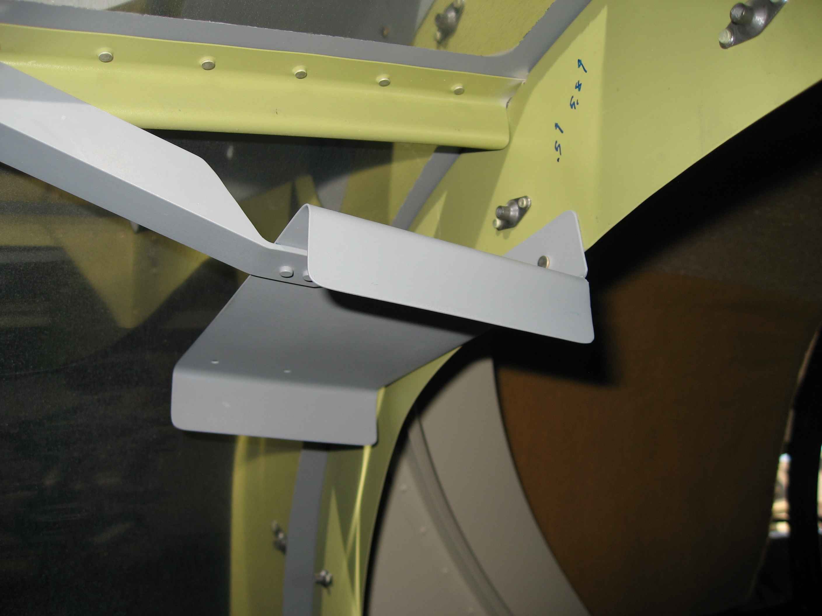
Here I have drilled a 3/8" hole in the bottom corner of the baggage compartment bulkhead (both sides), installed grommets, and ran the wires for the left and right wing strobes
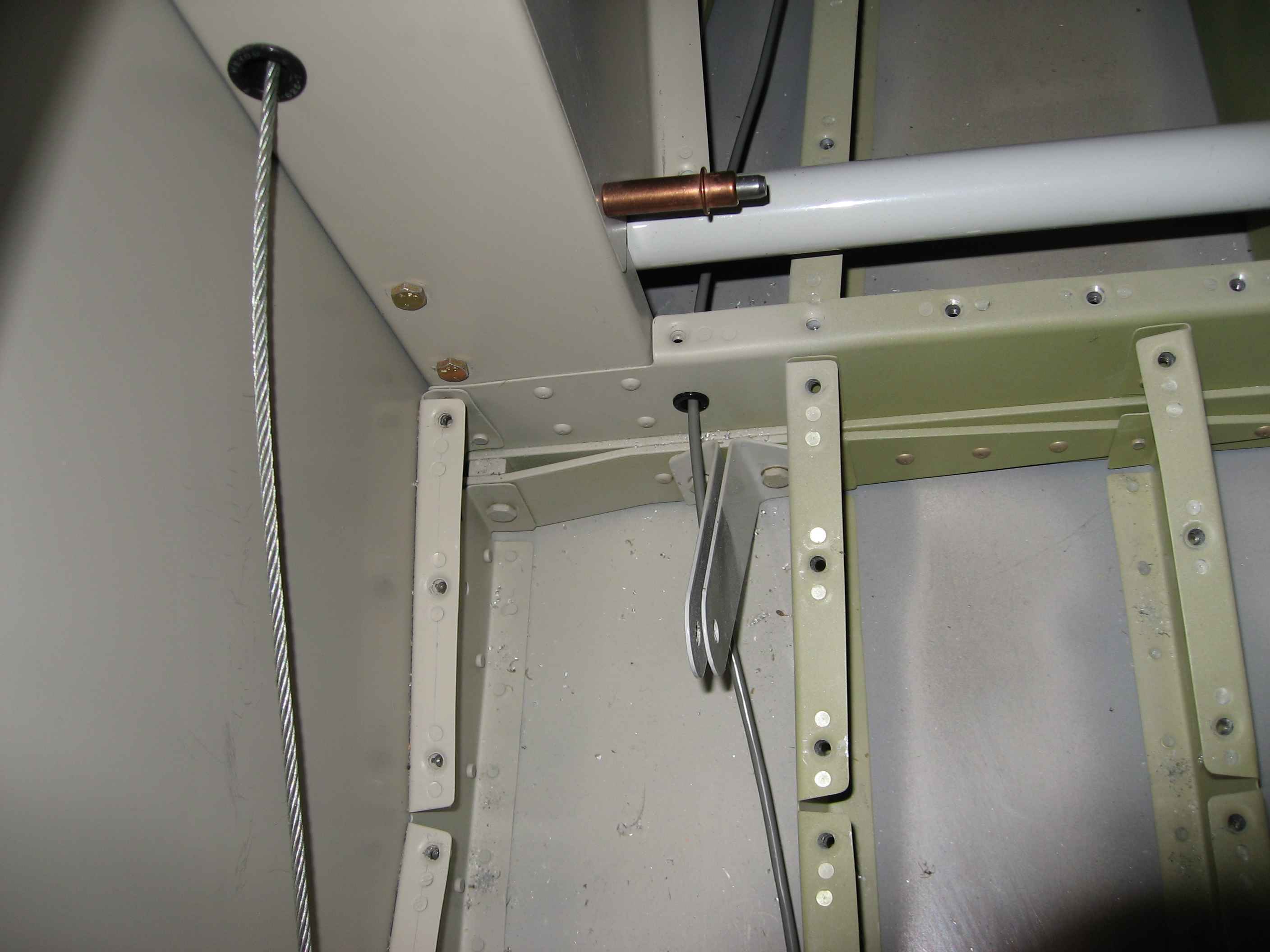
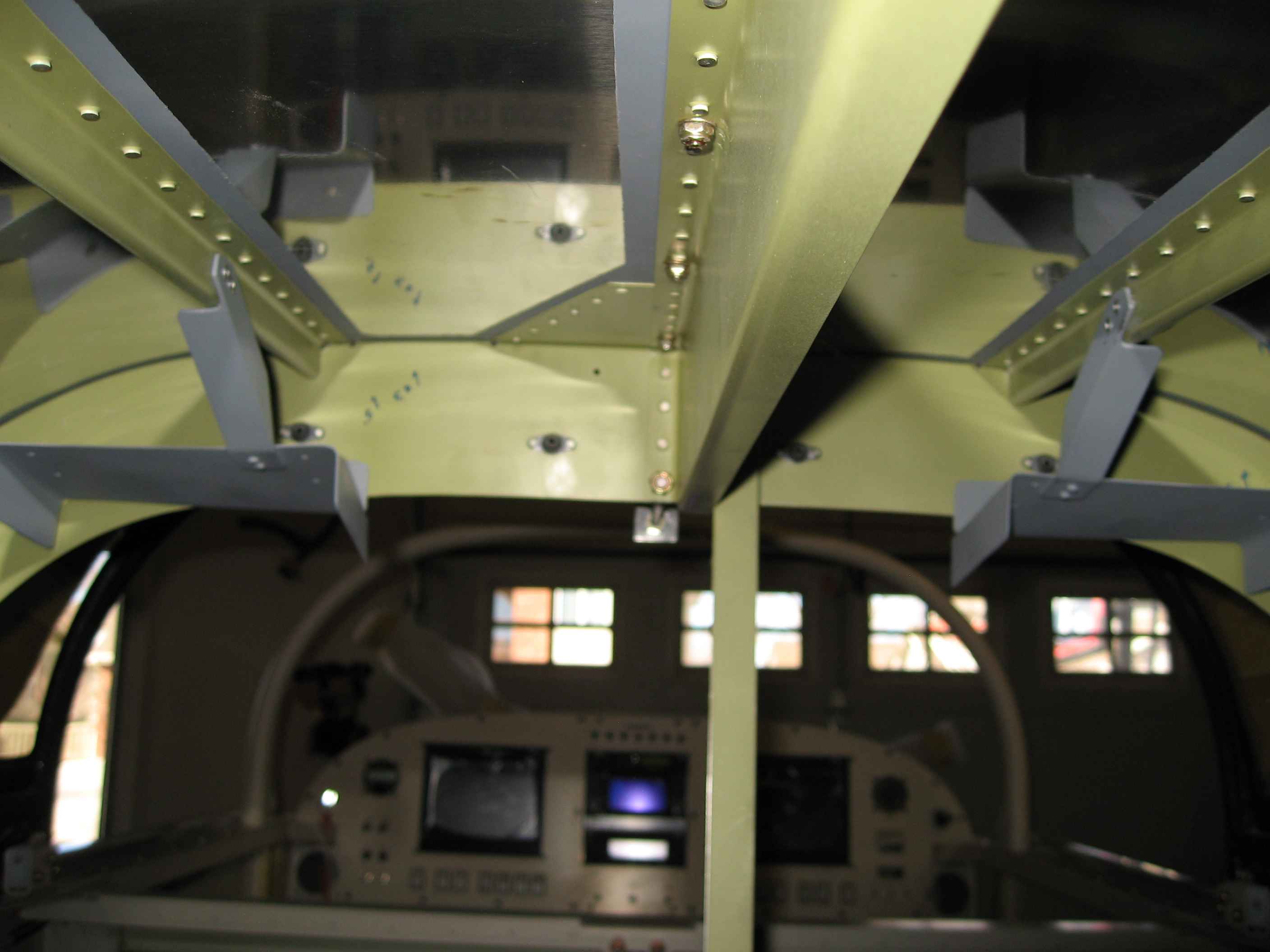
The wires were then secured with tie-wraps and tie-wrap mounts at various locations on the floor ribs.
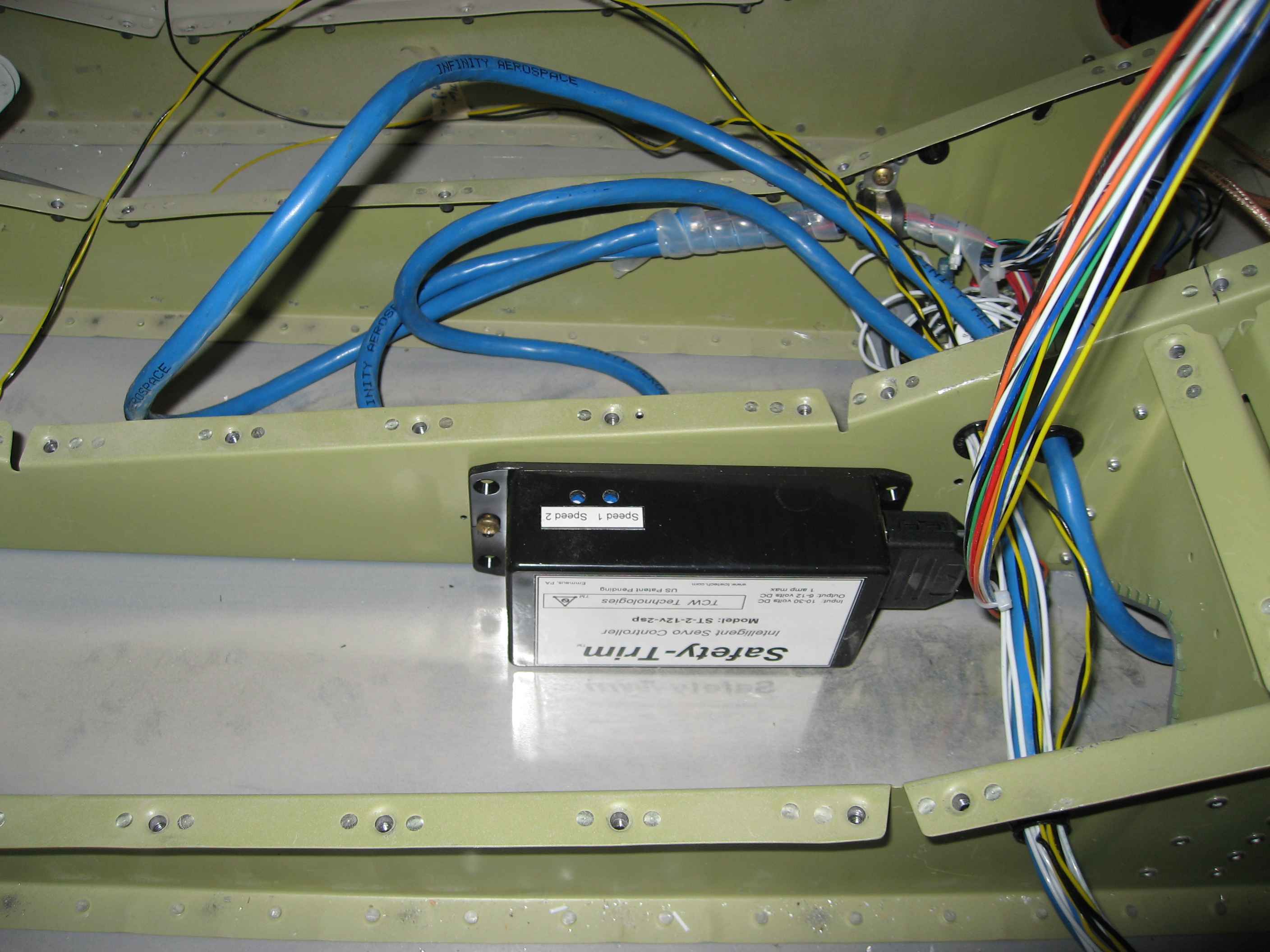
I then ran the power and ground lines for the strobe power unit and hooked things up to the strobe switch on the panel
I also begun re-wiring the terminal blocks for my sticks. I did not like how things were hooked up, and I need to make some changes to things like the starter and flap functions so that they are switched to ground, rather than 12V DC. This will require me to use some relays. I did not have any, so I placed an order from McMaster Carr