 |
January 6-7, 2007:
(2.0 hrs.)
I decided to go with an the
Trutrak Digiflight II VSGV auto pilot. I ordered the servos so
I could get them installed now. I will not order the auto pilot
brains until I am ready to work on the panel.
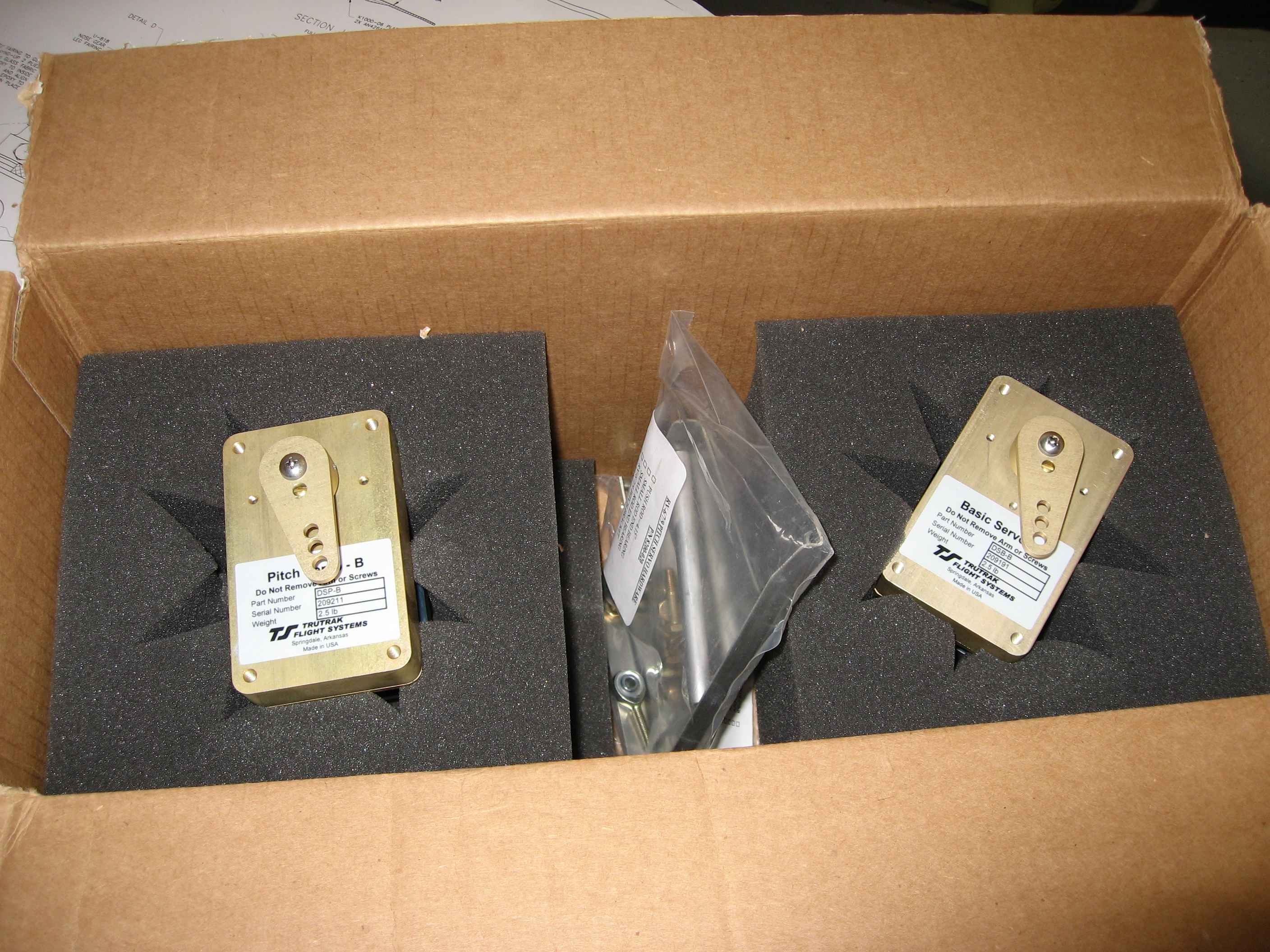
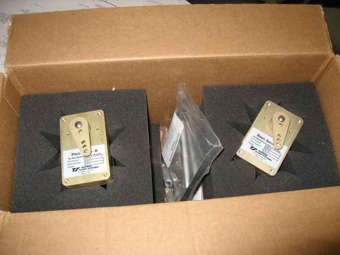
Here are the two servos. Pitch and Roll |
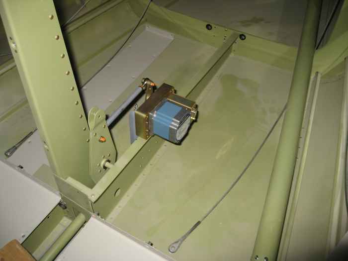 |
The pitch servo comes with the required
hardware to attach it to the elevator bell-crank rib.
Its a relatively simple process. I measured the setback for the
bracket to the bell-crank and identified the bell-crank rib rivets that
needed to be removed. With the rivets removed, I match drilled the
holes to the pitch servo bracket. The bracket and push rod were
then deburred, cleaned, prepped and primed.
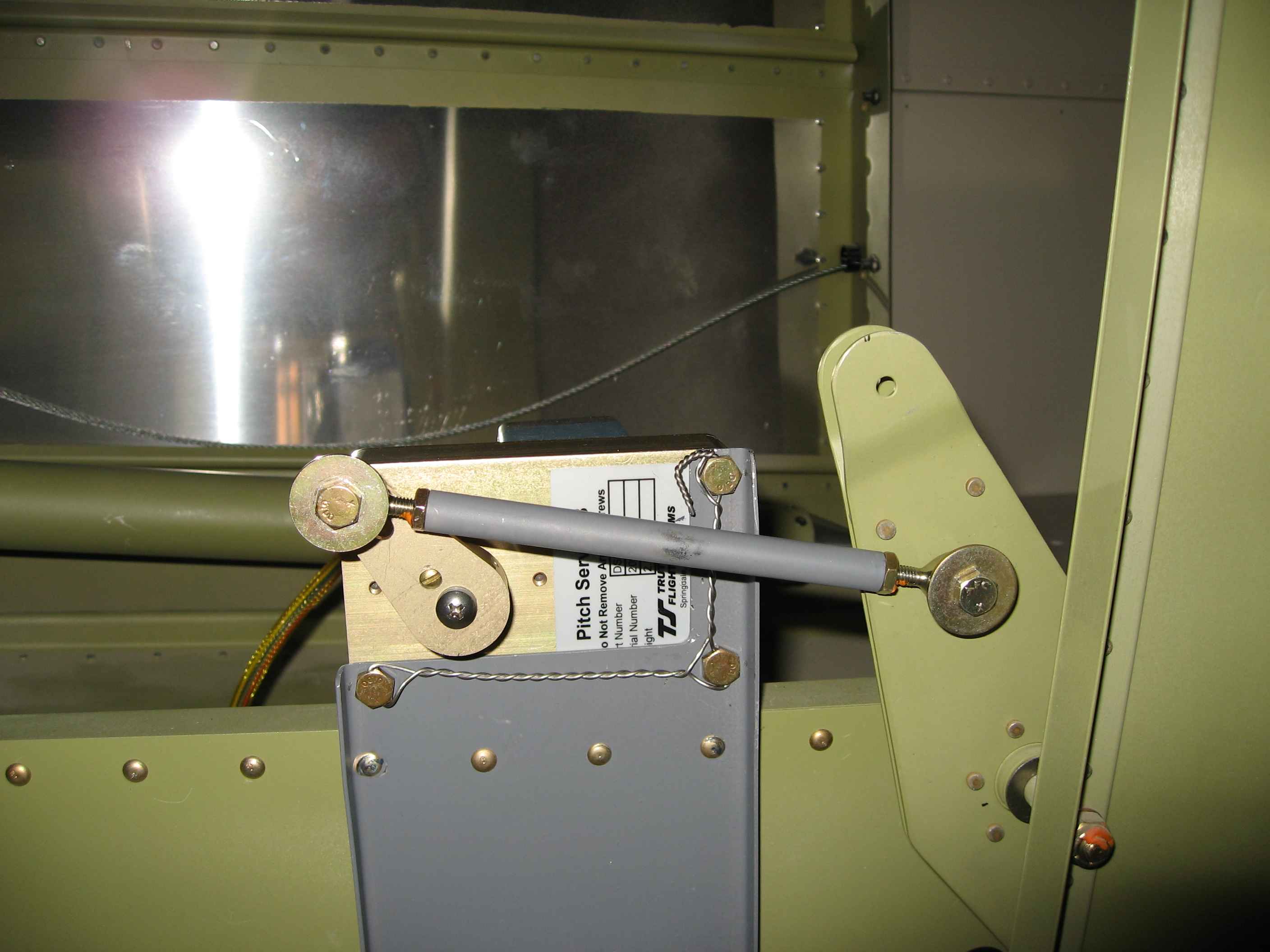
Here you can see the bracket with servo and pushrod attached all
attached. |
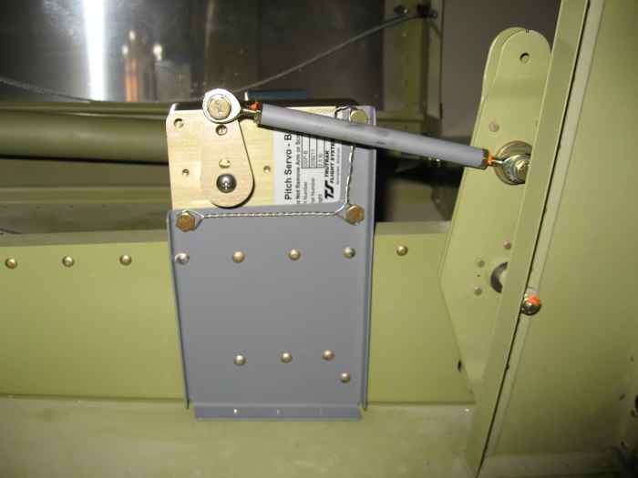 |
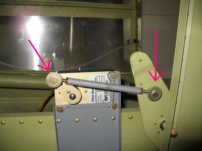
This is a shot showing the bracket setup.
I added a few extra attachment rivets lower on the bracket and then left
out the rivets that would attach it to the bottom skin. It seemed
plenty strong with the extra rivets I used.
My pushrod was at an angle to the aileron bell crank (can't tell from
this picture). I checked a few other builders sites and saw that
they had the same issue. Trutrak indicates that it is not a
problem. Some builders have used spacers on the servo arm to
correct the angle.
Also note I safety wired the servo attachment screws. This was
my first real hand at doing this. In these pictures I noticed a
bit of slack around a couple of the bolt heads, so I will probably redo
the safety wire. |
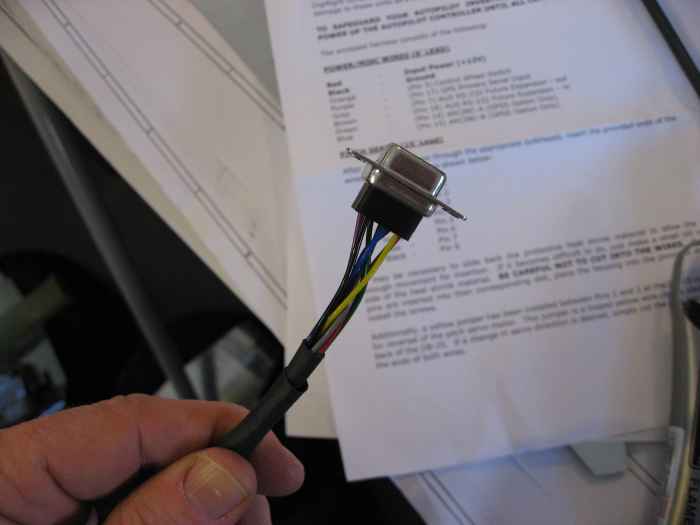 |
I went ahead and ran the wiring harness
for the auto pilot servo. I bought a pre-fabricated harness from
Affordable Panels, so it was just a matter of running the wires and then
putting on the DB connector.
Here I have installed the wires into the correct pin positions of the
connector |
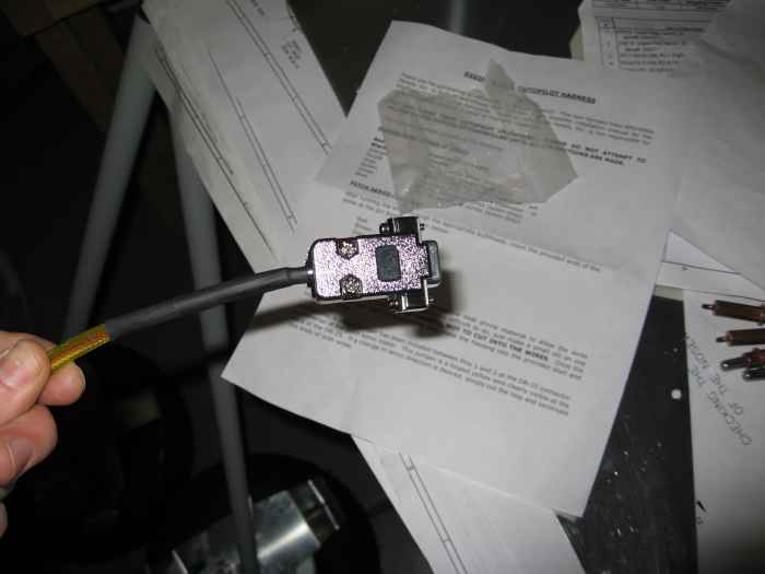 |
Added some heat shrink and installed the
connector case. Done. |
 |
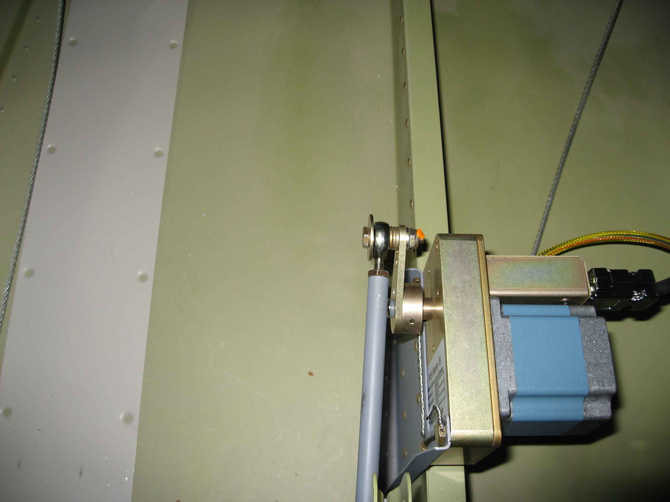
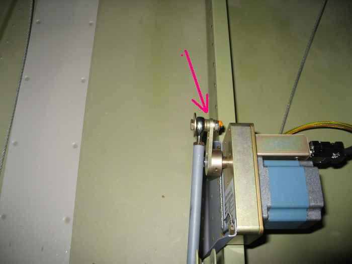
After viewing a few more builders sites, I
decided that I would change my pitch servo push rod setup slightly.
First, instead of using the large safety washers as on offset for the
rod-end on the bell-crank as per Trutrak instructions, I decided to use
regular washers in that position. I the used the safety washers
for their intended purpose on the outside of the pushrod ends
(pictured). |
 |
I also added 3 washers between the pushrod
and the servo arm to decrease the pushrod's angle to the bell-crank.
I had to replace the AN3-7 bolt with an AN3-10 bolt to accomplish this.
I felt this provided a happy medium between putting a full spacer in to
make the push rod run straight with the bell-crank (which Trutrak
recommends against), and leaving the current angle in which was causing
a little bit of binding. |
 |
November 20
- December 3, 2007:
(12.0 hrs.)
I have been spending quite a bit of time working on my electrical
system design. Since I will have an electrically dependent engine,
as well as all electric panel, I have decided to install a highly
redundant electrical system. I am going with a dual battery and
dual alternator setup. I will be closely following the Bob
Nuckolls Aeroelectric
Z-14 design. My electrical design can be found
here. Ad
|
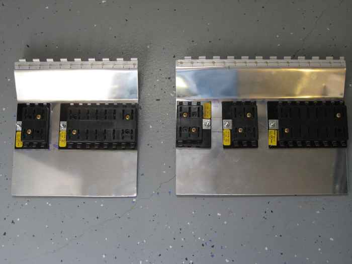 |
I decided to go the non-traditional route
and use fuses instead of circuit breakers. I basically bought into
Bob Nuckolls reasoning on the subject in his book the 'AeroElectric
Connection'.
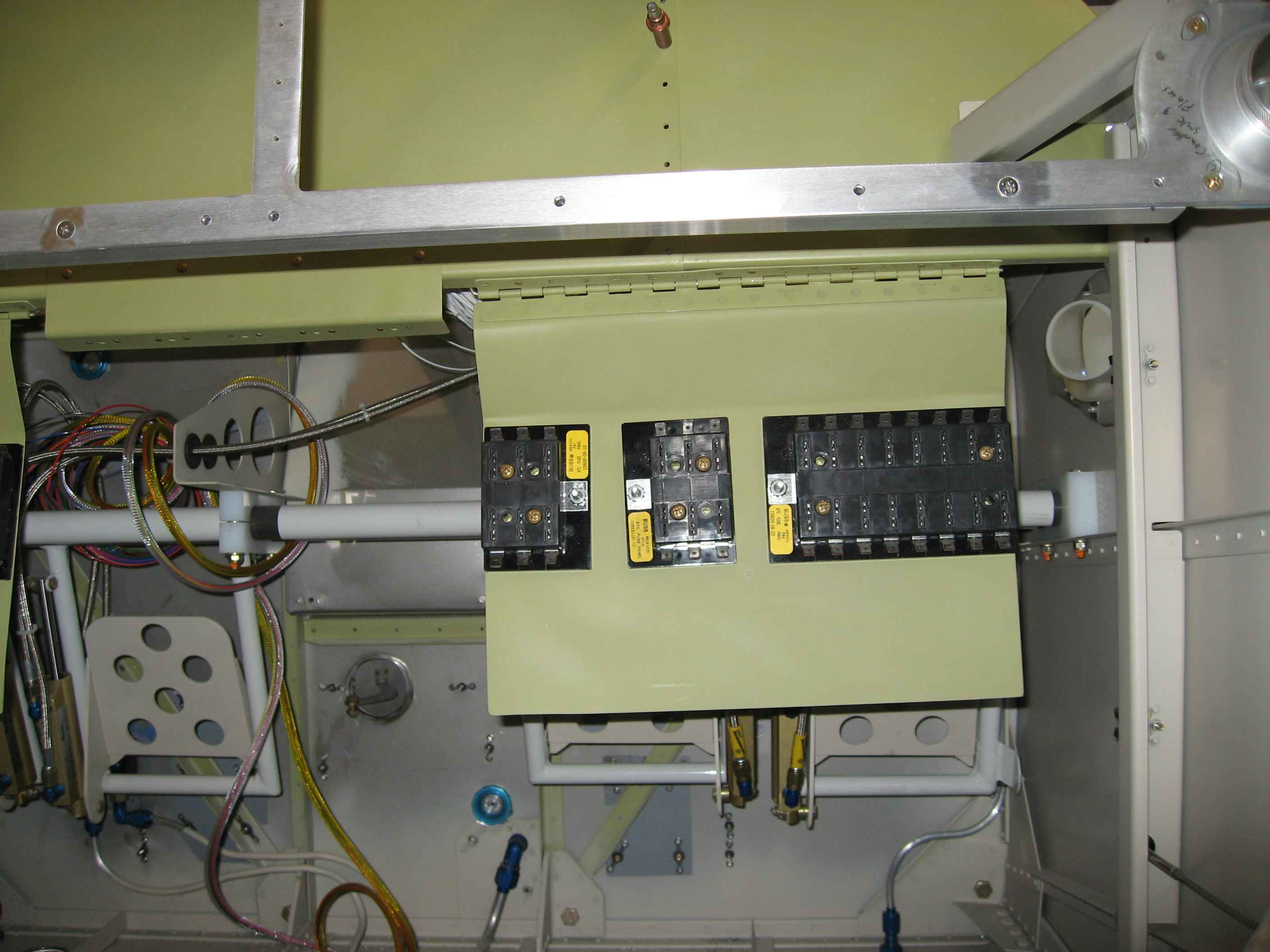
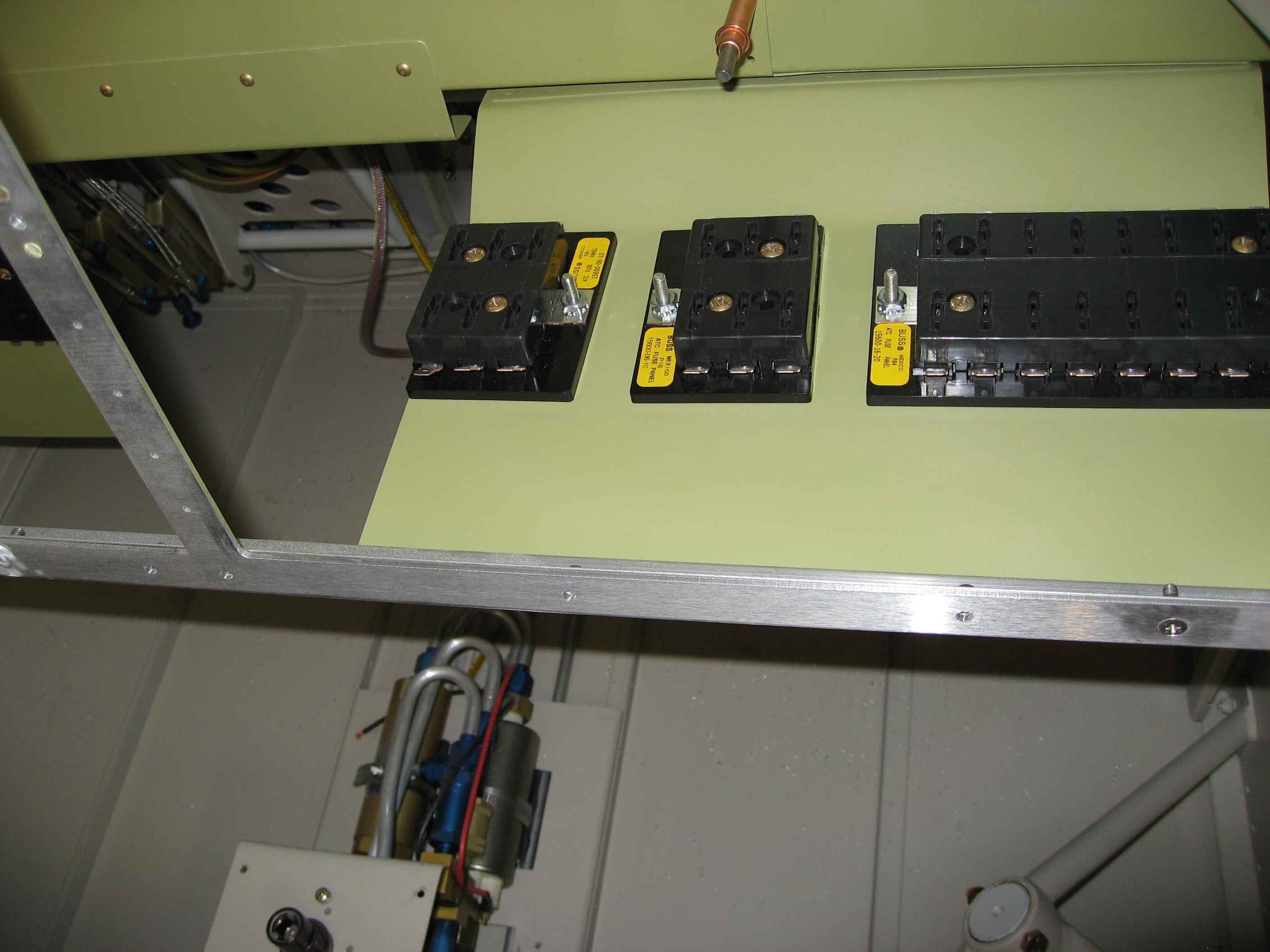
With fuses in mind, I bought some fuse blocks from BandC and then
fabricated these hinged panels that will sit under my panel. |
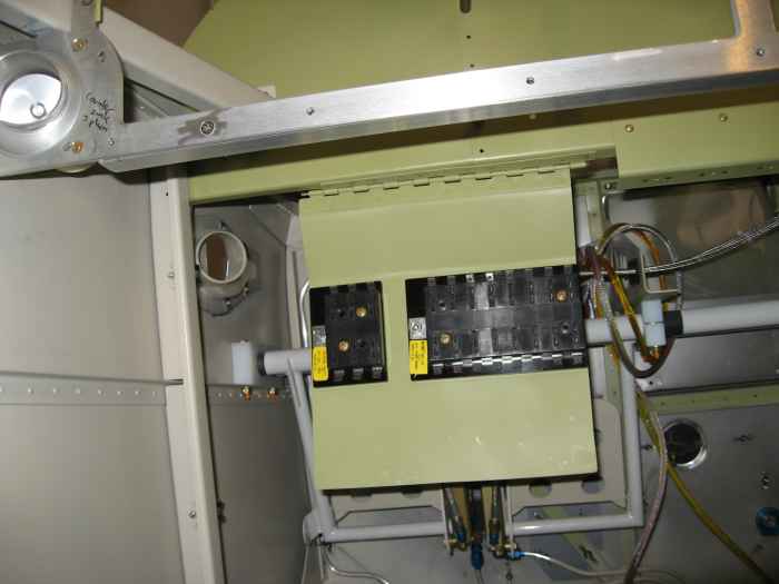 |
Here is the left side panel installed via
a hinge to the sub-panel. The reason for the hinge is to provide
easy access for troubleshooting and changing fuses. I do NOT
expect to do this in the air, only after I am down safely on the ground.
The left side fuse panel houses the FADEC A Bus and the MAIN Bus. |
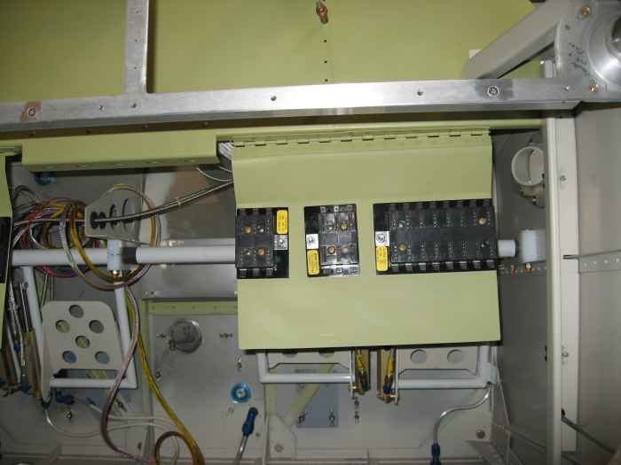 |
Here is my left side fuse panel. It
houses the FADEC B Bus, AUX Bus, and BATT Bus |
 |
Here is the left side panel swung up in
the closed position. I still need to find a camlock fastener that
I can use to hold the panels in the closed position securely. |
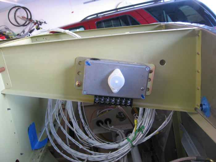 |
Installed the B&C LR3 regulators for my
alternators. I have two of these regulators because I have two
alternators.
Here is one of the regulators installed on the right side rib near
the firewall. The second one is installed in the same position on
the left side. |