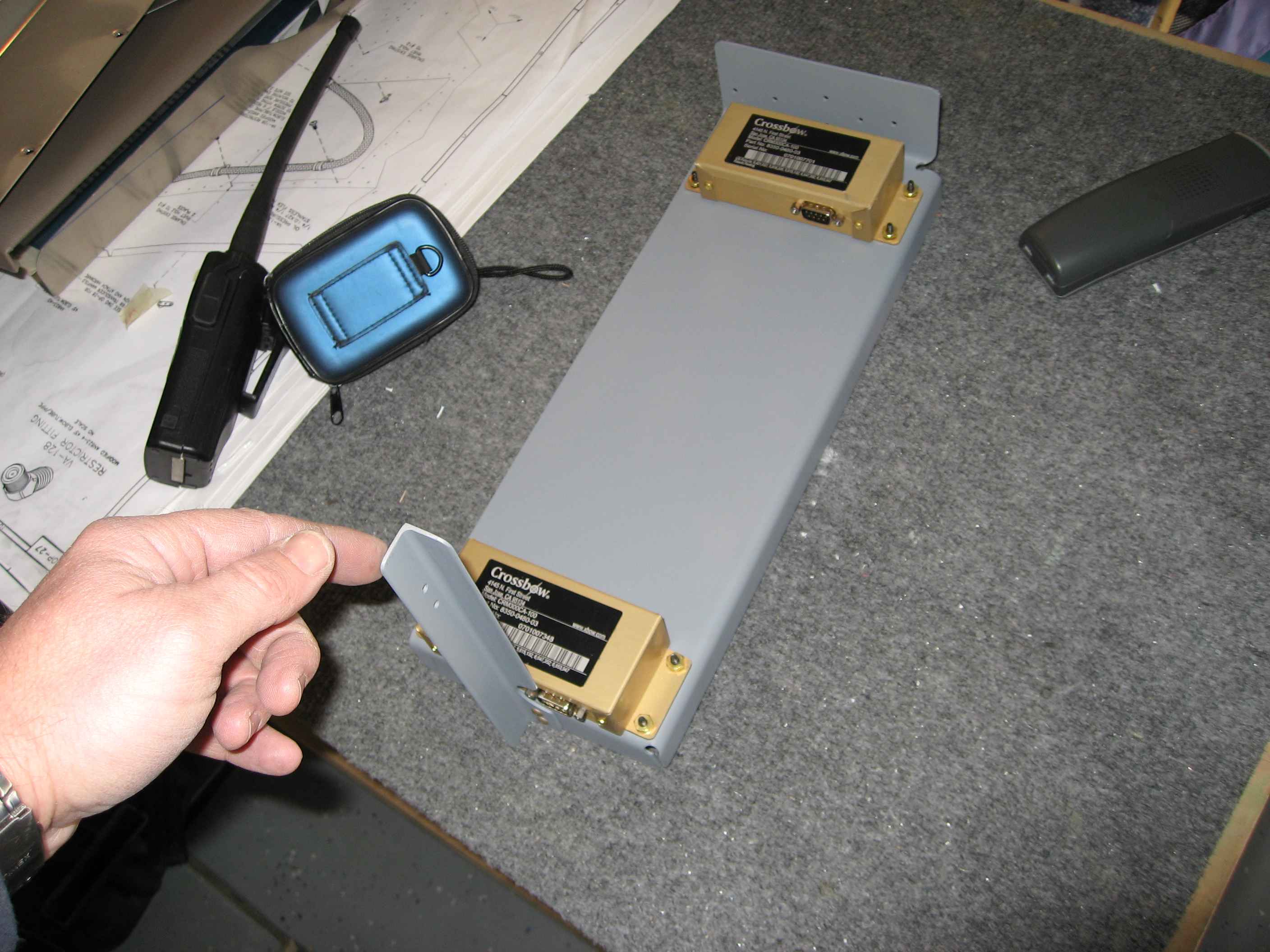
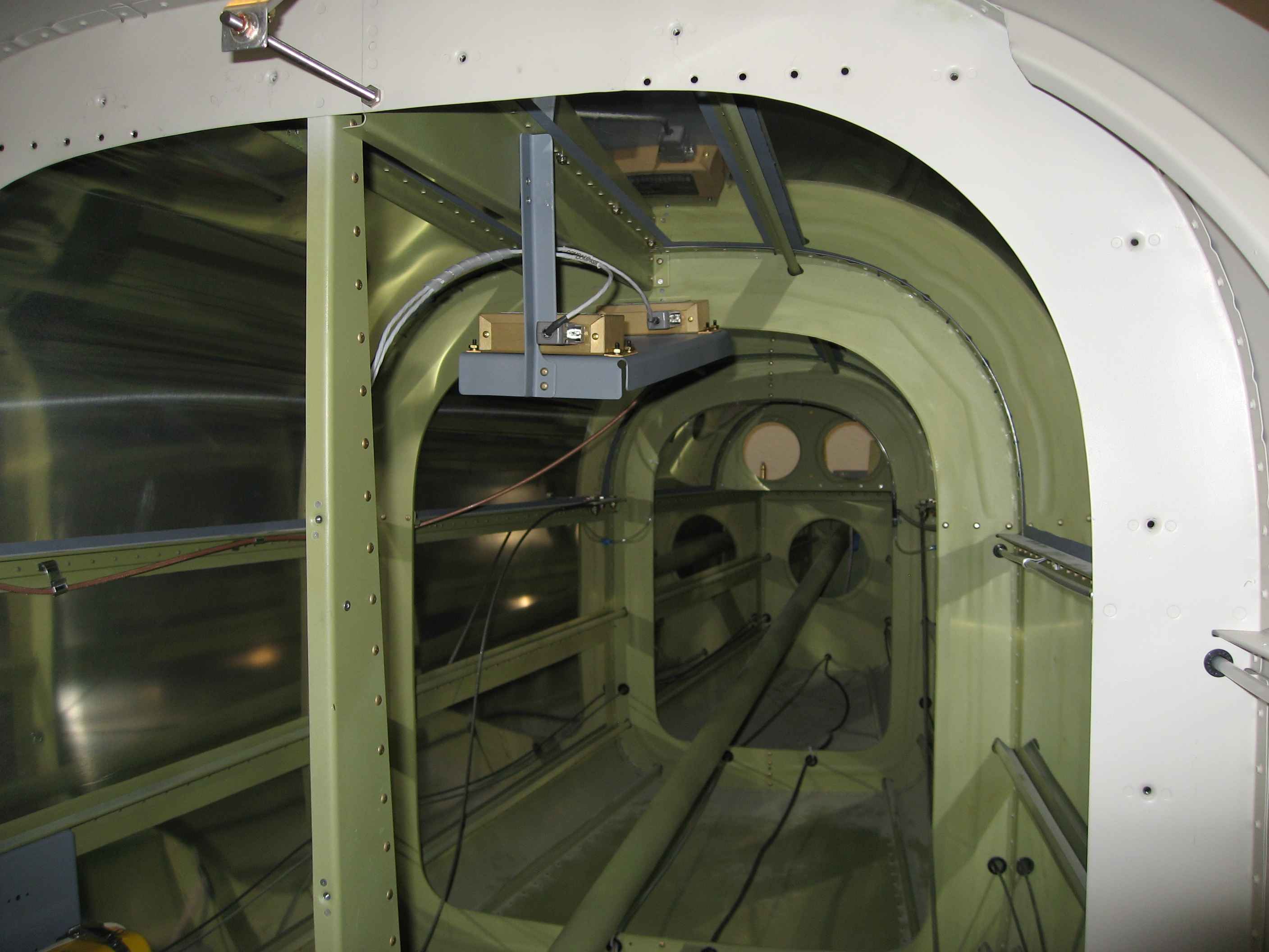
Ever since I installed my magnetometers and saw a huge difference in heading readings (!00 degrees) between the two EFIS displays, I have been concerned about their placement. I was told that the discrepancy in readings would go away after I ran the magnetometer alignment program, but I was still concerned. The fuselage is currently in my garage, so I cant really run the alignment routine because the fuselage needs to be rotated a full 360 degrees several times. I decided to see if I could determine what was causing the magnetic interference. I took my son's camping compass and began moving it slowly about the areas behind the baggage bulkhead (where the magnetometers are installed). I immediately noticed that the compass needle was drawn to the steel bolt that holds the sliding canopy center track in place. The bolt is right between the two magnetometers. I also observed that there was little magnetic interference one bulkhead further aft from the baggage bulkhead. I then decided I would remount my magnetometers in that location. that required a new mount to be fabricated. Pictured is the new mount.
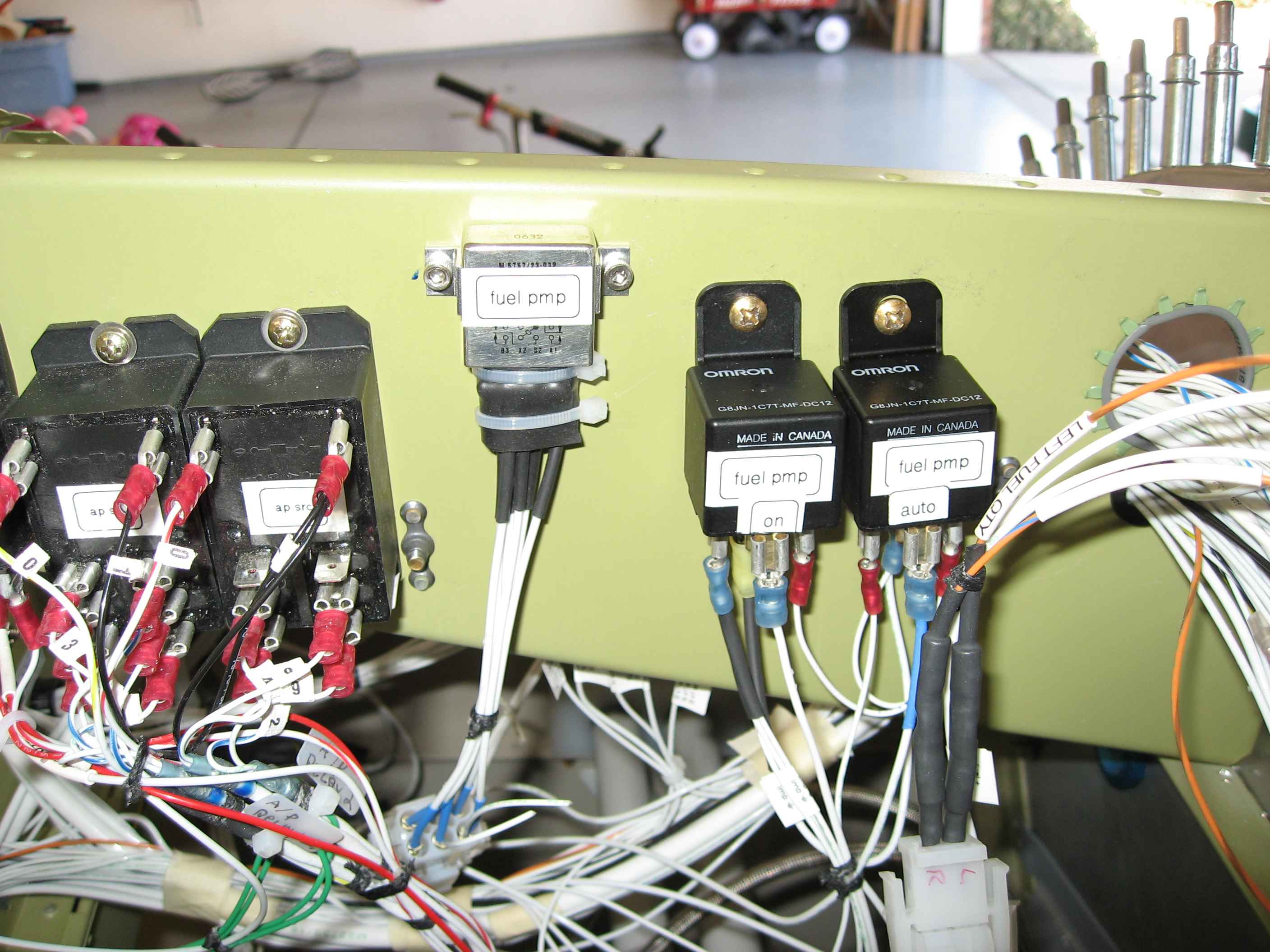
Finished the wiring of the fuel pump relays and rocker switch in the panel. Because I am using a special 3-way rocker switch that only works on low amperage, I needed to install a couple additional relays to handle the high amps of the fuel pump. Had I just gone with regular toggle switches, I could have avoided using many of these relays. Oh well, I like the looks of the Rockers better.
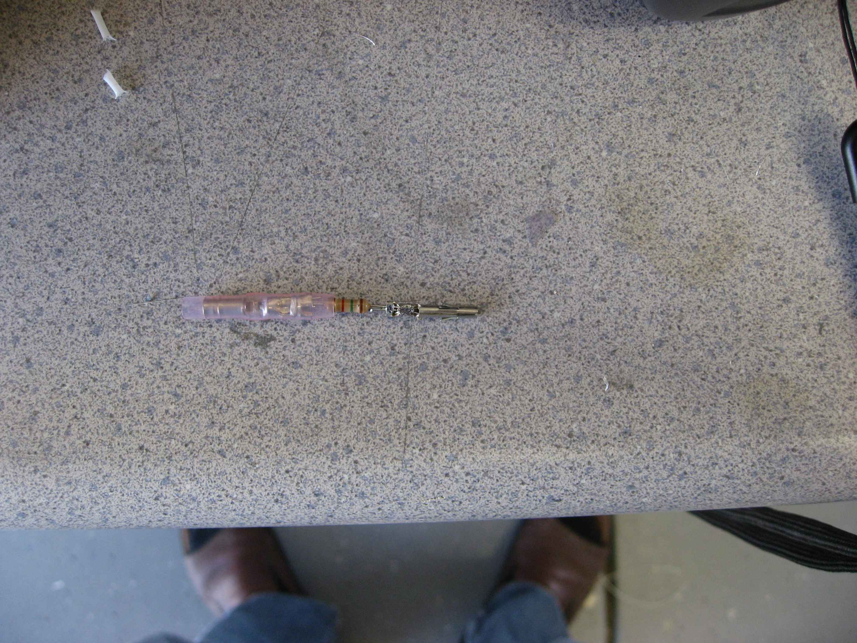
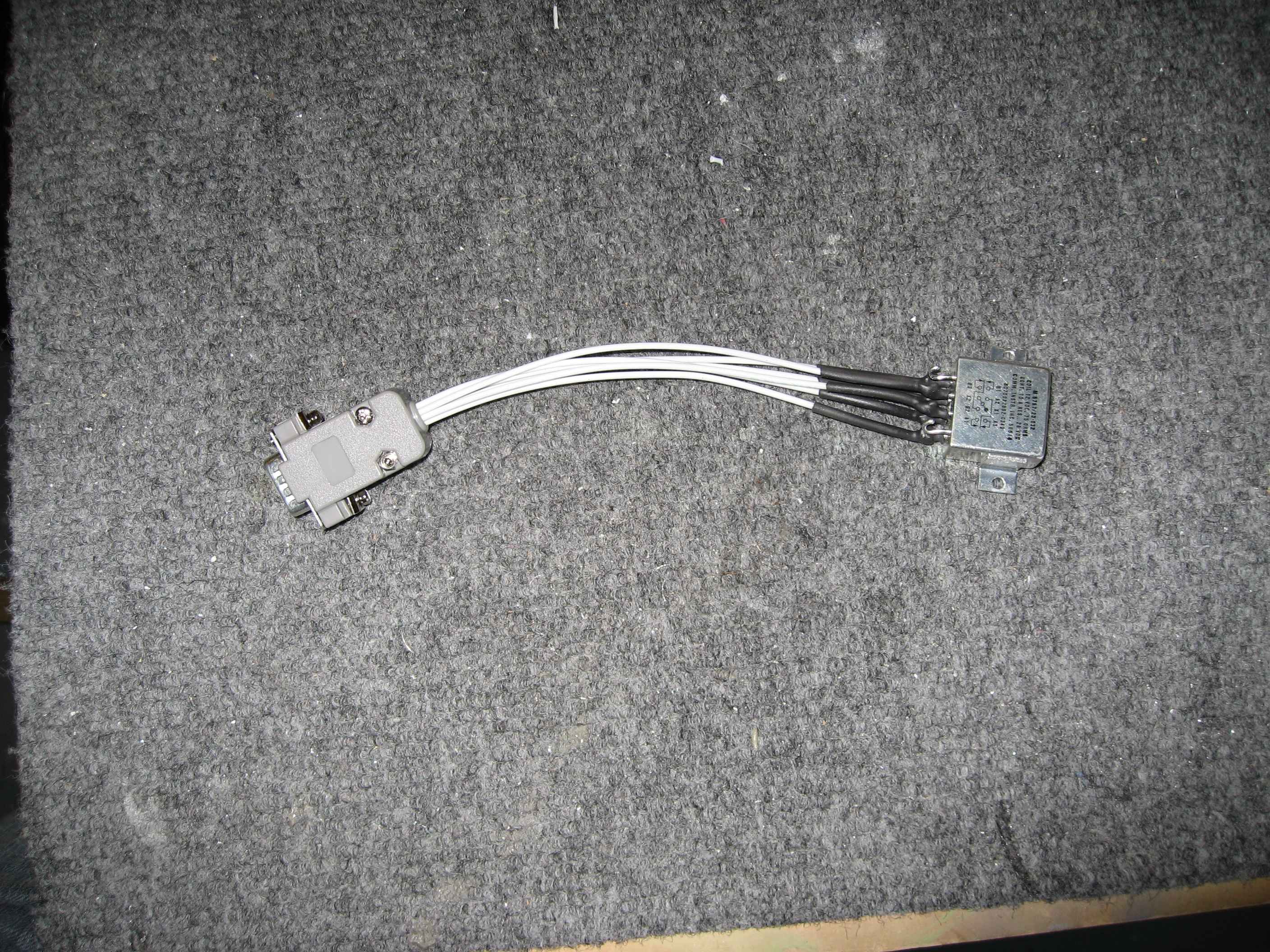
Here I have crimped (and soldered) one of the supplied resisters (I think it was 1.2K ohms) to the Molex pin.
Here is the finished wire before it is inserted into the Molex housing.
The dimmer units I purchased from SteinAir are two channel units giving me a total of 4 channels, so I will just not use one of the channels.
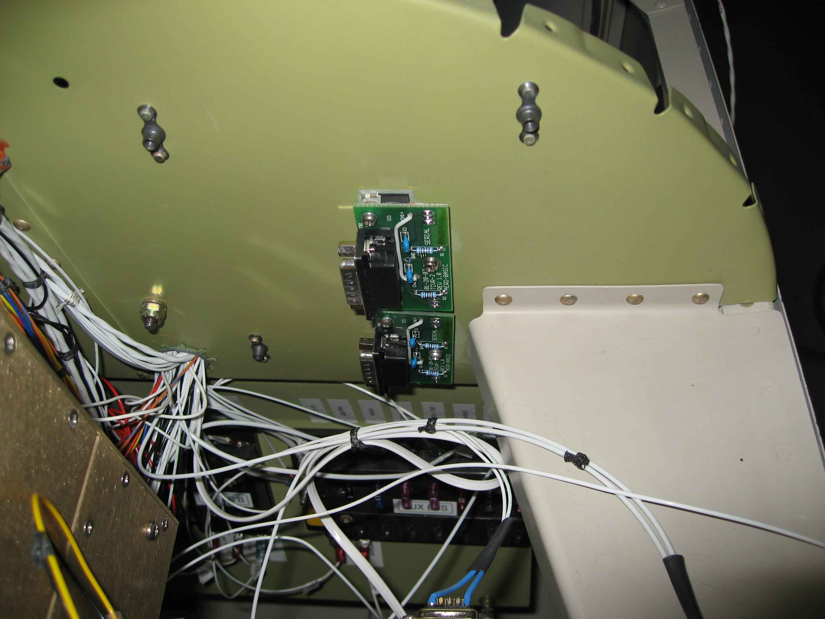
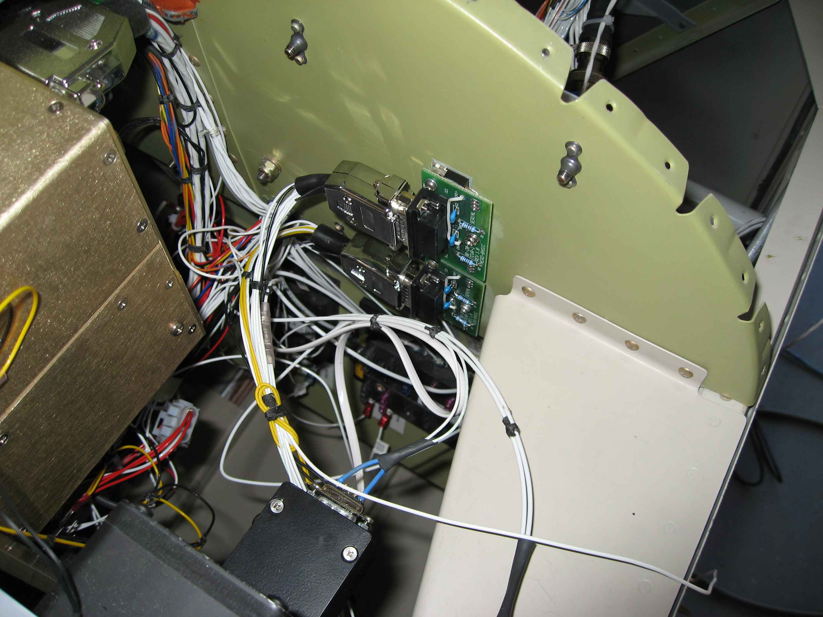
These dimmer control units can put off quite a bit of heat when set at low dim levels, so the idea is to mount them to a metal structure allowing the heat to dissipate.
Here you can see I have mounted them to the right side of the sub-panel structure.
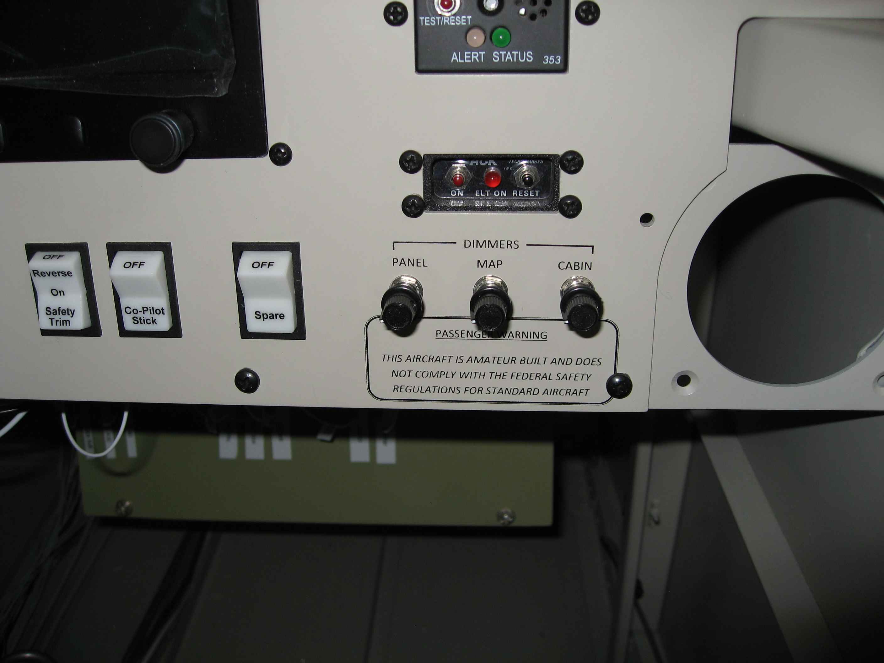
Here I have wired the DB connectors and made the appropriate runs to the panel for the dimmer controls. One thing to point out is that I installed a Dimmer power control switch on the panel. Flipping this switch on sends power to the dimmer controllers which then sends power to all the pertinent things I need lighted. If I do not want something lighted during night flight (e.g. the map light), I just turn the map light dimmer control all the way down.
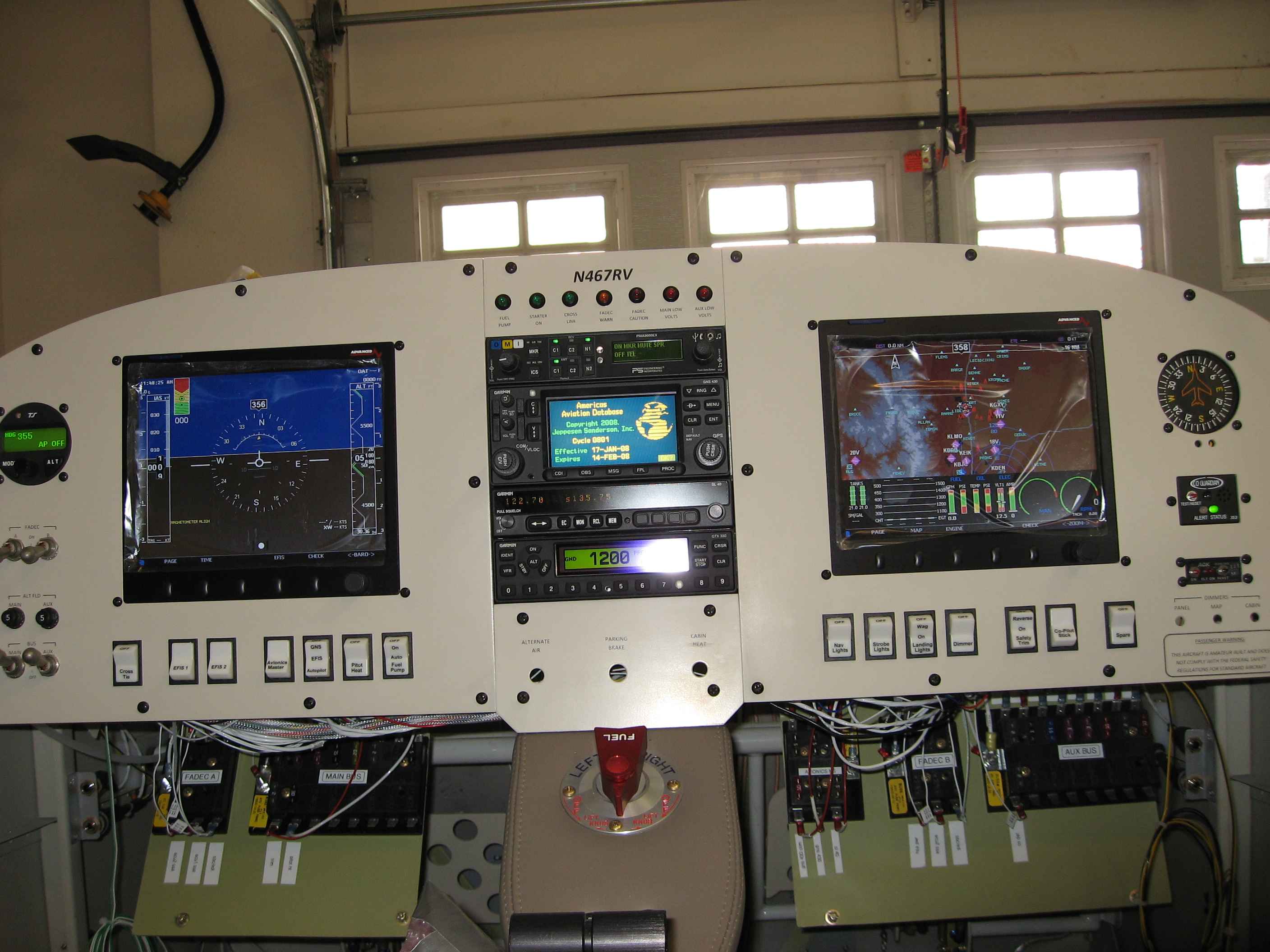
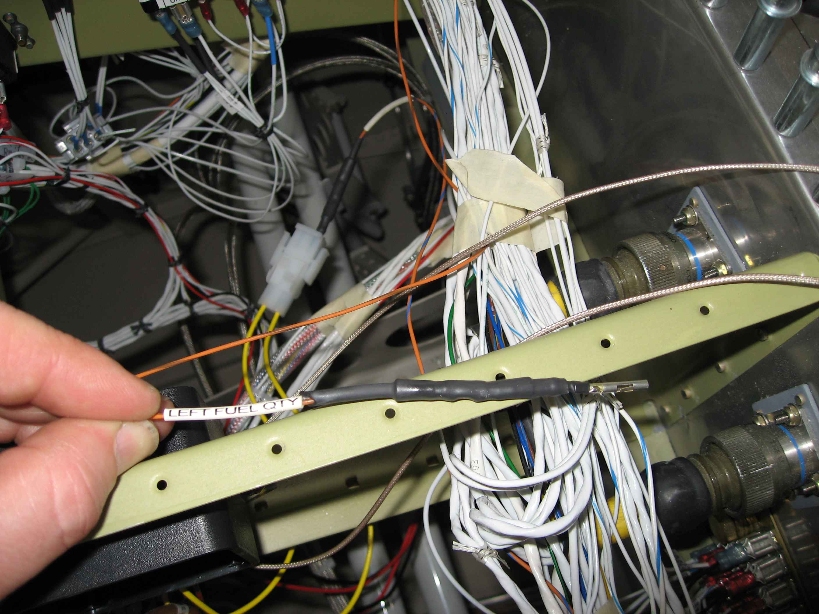
I ran a test of the dimmer for my panel mounted items and found out that my rocker switches were missing their internal LEDs! Doh! I called SteinAir and they said they would send some right out. I did get to see how the dimming control worked on the PMA 9000 and the Vertical Card Compass. It seems the PMA 9000 is much brighter than the compass lighting. I think I will experiment with inserting a resister inline with the PMA 9000 to adjust its lighting level.
I can't test the dimming of the glare shield or map lights yet, as I have not installed those. I believe those items represent the last bit of wiring left for the cabin/panel.