 |
March
14 -
April 6, 2008:
(40.0 hrs.)
I have been up to my eye balls in wiring. I have not made any
log entries in a while because I have been busy doing the same thing...
"connect this wire to that, test, and do it all over again". I also do not have a lot of pictures.
The good news is that I am almost completely done with my wiring in the
fuselage.
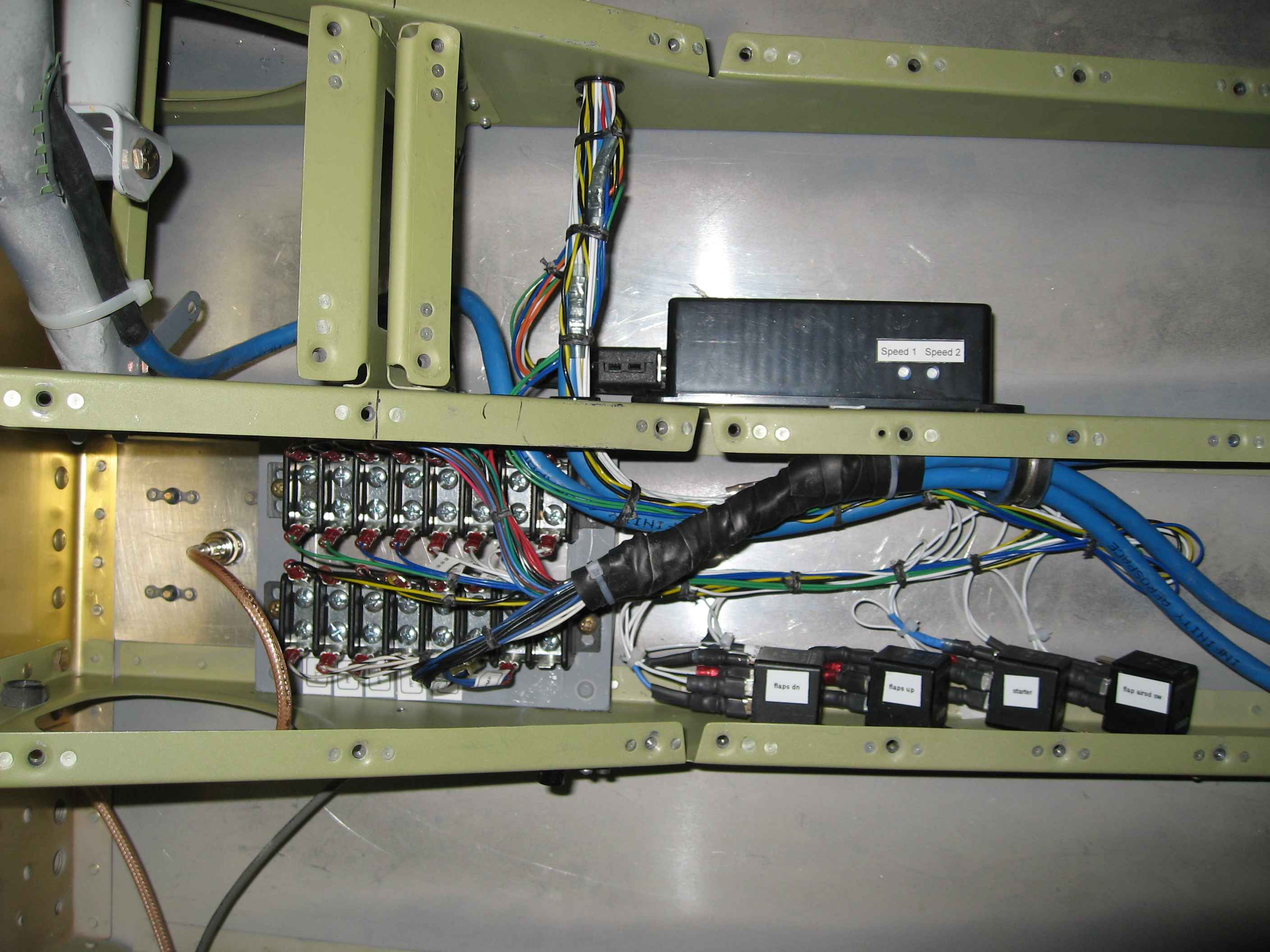
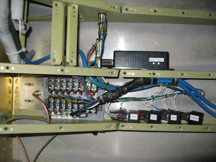
Here you can see the terminal blocks and relays under the pilot seat
for both stick grip functions. This whole setup was a pain to
wire. I can see why many builders skip adding functions to their
grips. I used the relays to convert some of the stick functions to
'switch-to-ground' rather than 12V. This allowed me to then easily
add a co-pilot disconnect switch by placing it across the grounds.
Functions on the stick include: engine start, aileron trim, elevator
trim, flaps, PTT, and Auto Pilot disconnect. I was going to also
add the fuel pump switch, but decided not to since the FADEC system
requires a 3-way switch (off-auto-on). I also wired the flaps into
the speed switch for the safety trim. This will keep the flaps
from being accidentally deployed when flying above 100 knots.
|
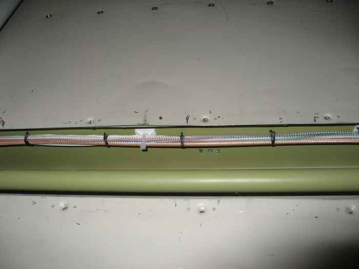 |
With all the wiring complete from the
sticks to the tail, I decided to start bundling the wires using black
waxed lacing. I then secured the wire bundling using wire ties and
adhesive backed zip tie mounts. I popped riveted the zip tie
mounts in place rather than rely solely on the adhesive tape.
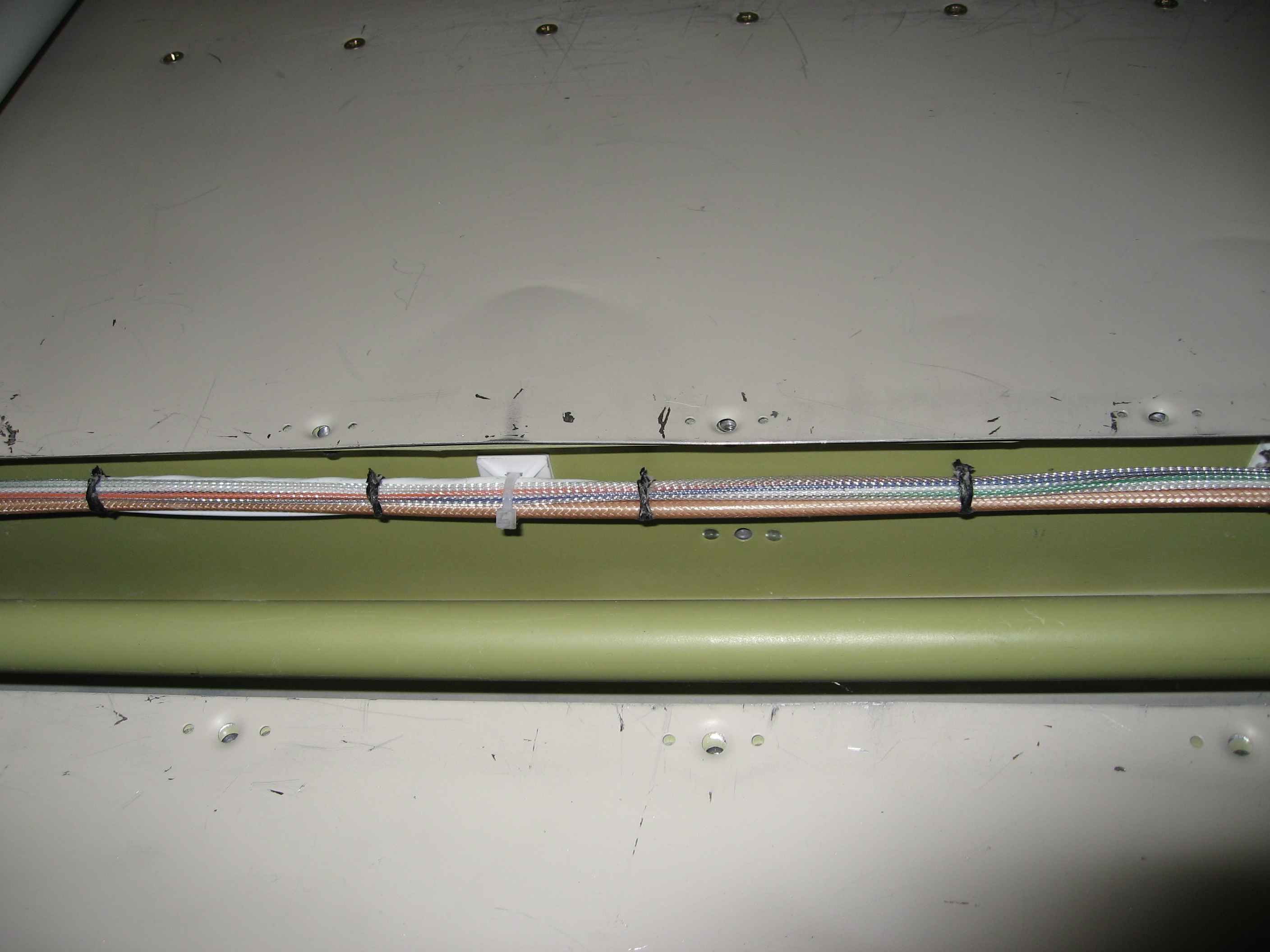
This is a shot of the wire bundle running along the left side of the
elevator center section control rod. There is also a bundle on the
right side. Please ignore my scratched and bent up baggage floor.
That is the result of climbing around in the baggage compartment and
laying tools in this area. I will take the bends out prior to
closing the tunnel, but I will not bother repainting, as this will be
covered with carpet. |
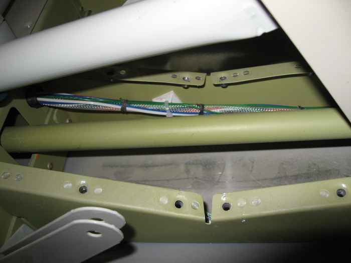 |
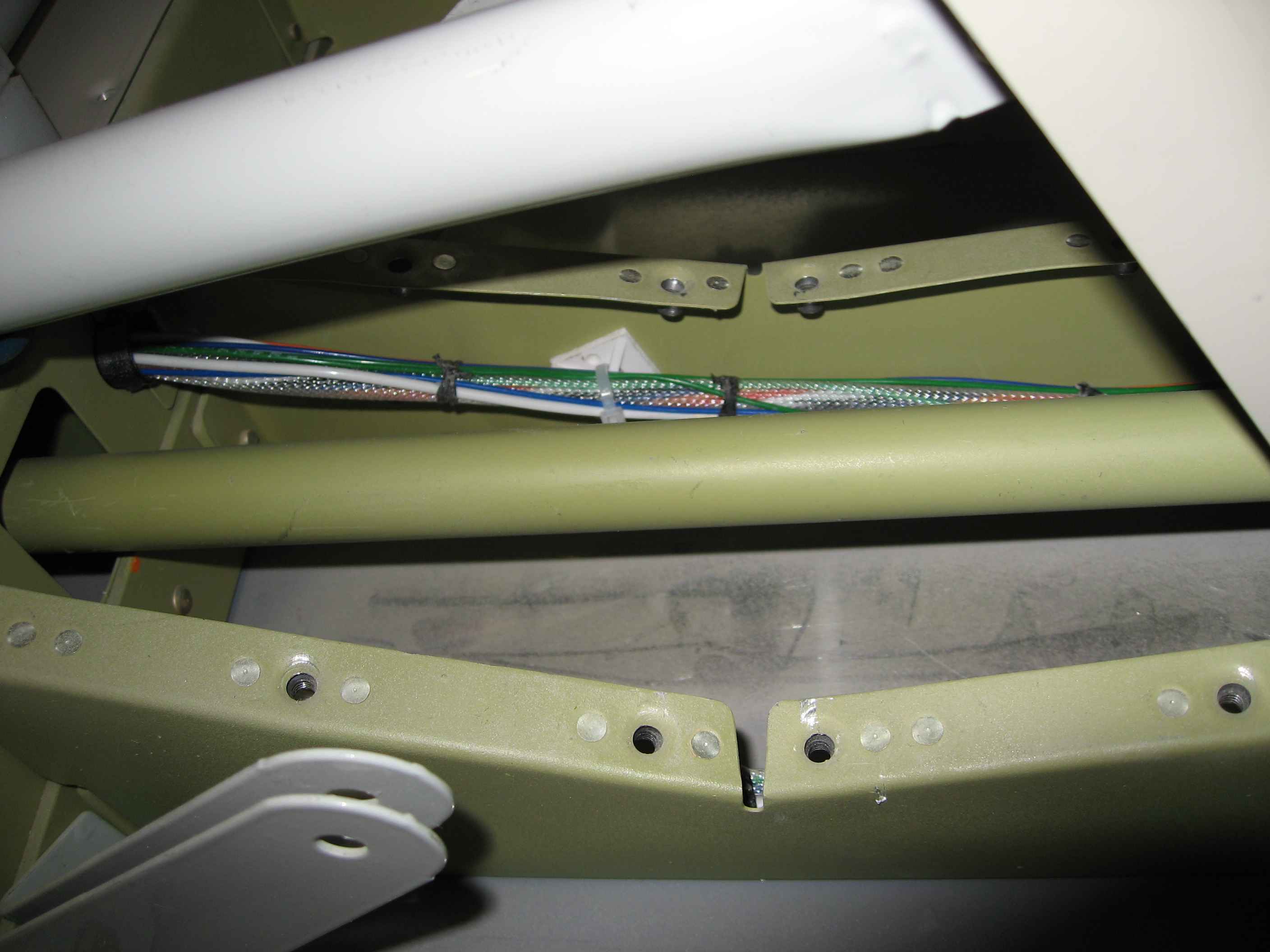
Here is a shot of the left side bundle as
it passes under the flap weld mount. |
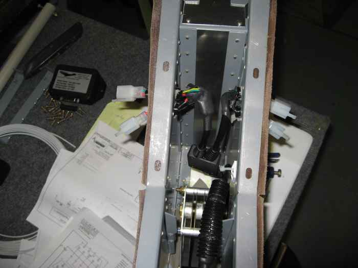 |
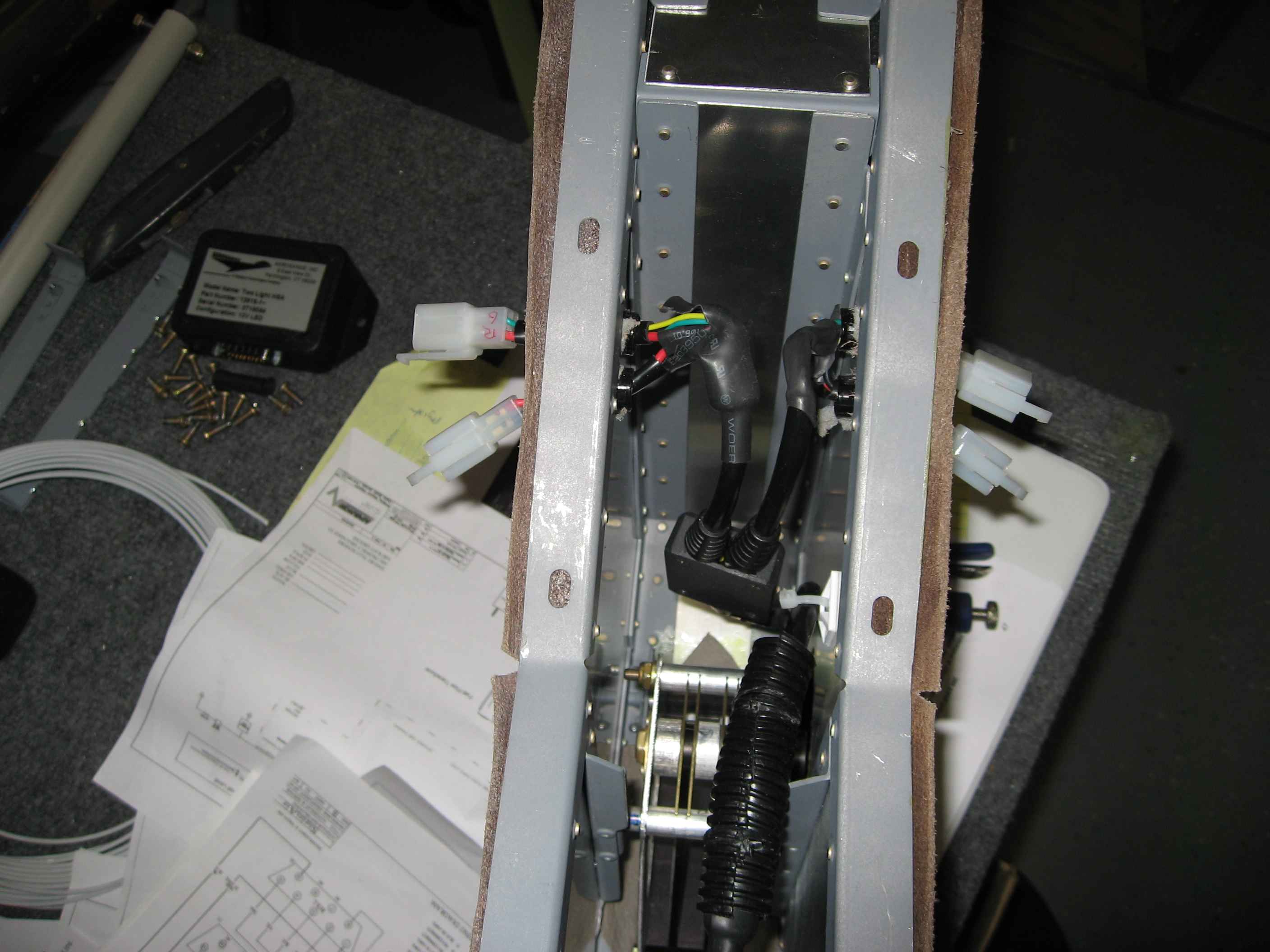
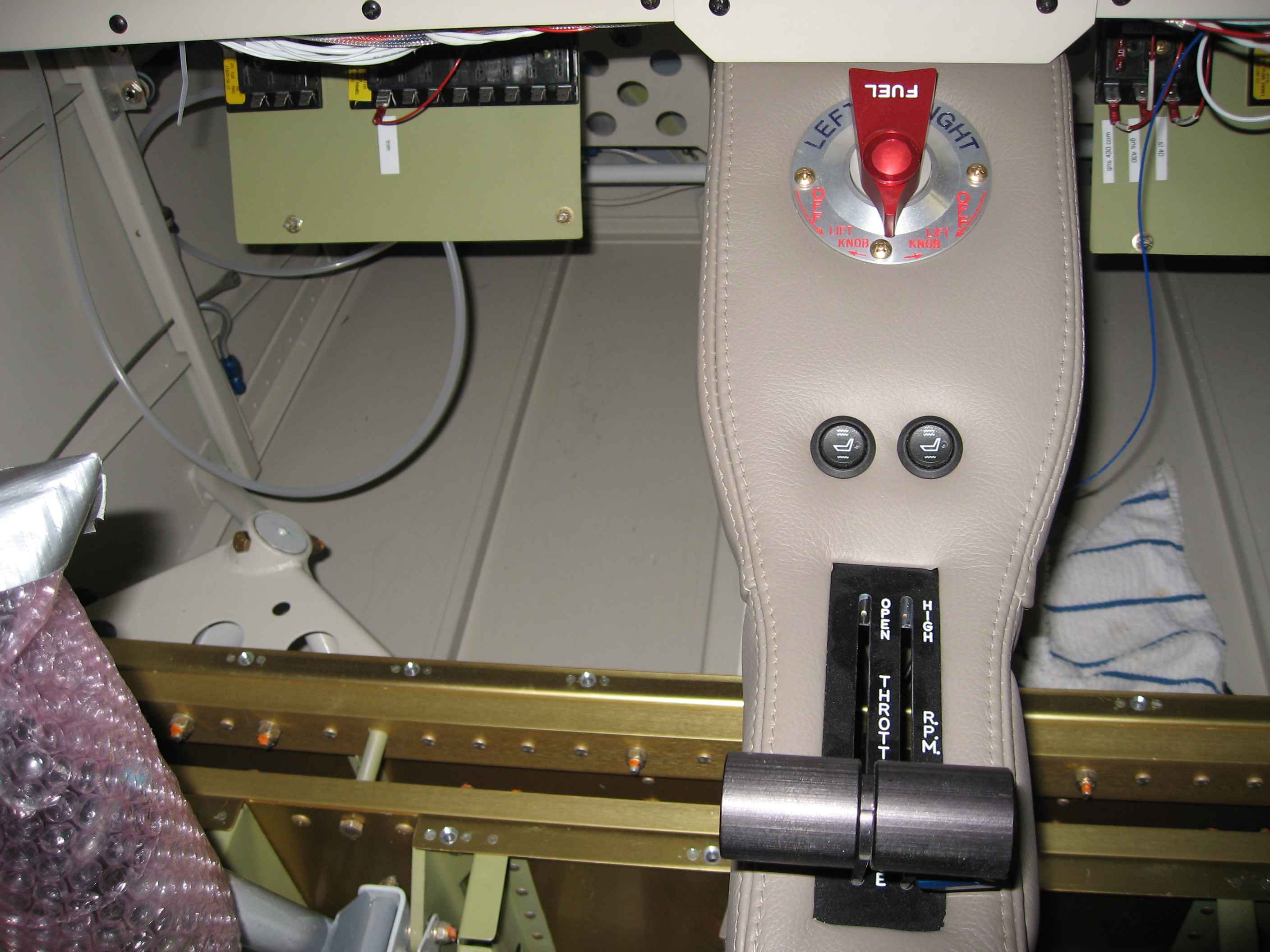
Switching to something different, I spent
some time figuring out the wiring runs for the seat heaters. I
wanted the controls for my seat heaters in the center console. The
wiring harness that came with the seat heaters was very long, length I
would not need if everything was in the center console. I spent a
fair bit of time cutting the harness down to size and re-using the
connectors it came with. I then installed the wires in the center
console and secured everything so it would not interfere with my
throttle and prop controls. This is a shot looking into the console
from its underside. I ran the seat heater connectors out the sides
of the console, down low where the wires will be hidden under the seat
bottoms. |
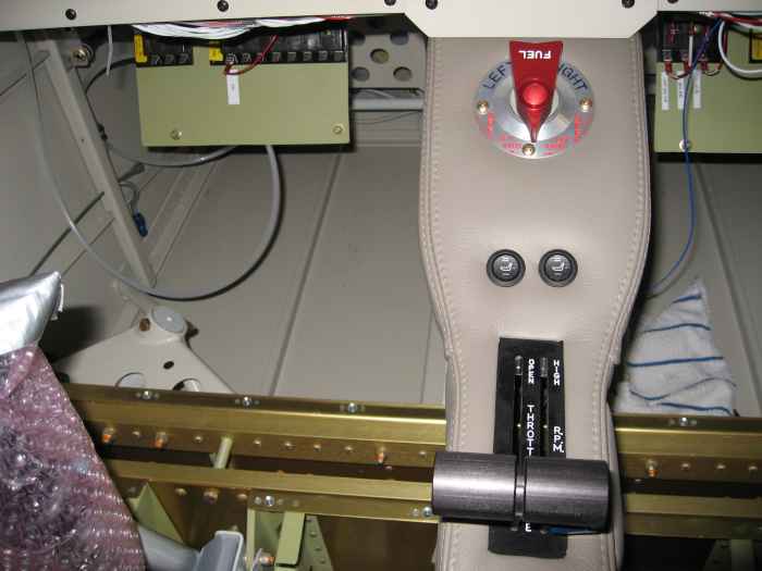 |
Here is a shot of the center console
placed in position. The two round buttons are the seat heater
controls for the pilot and co-pilot. Power comes from the bottom
center of the panel where I tied up the power and ground lines and
installed a Molex connector. |
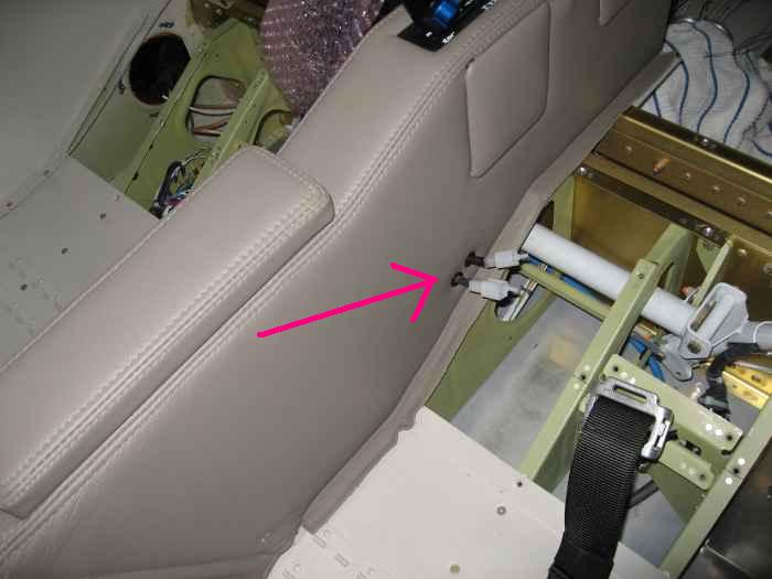 |
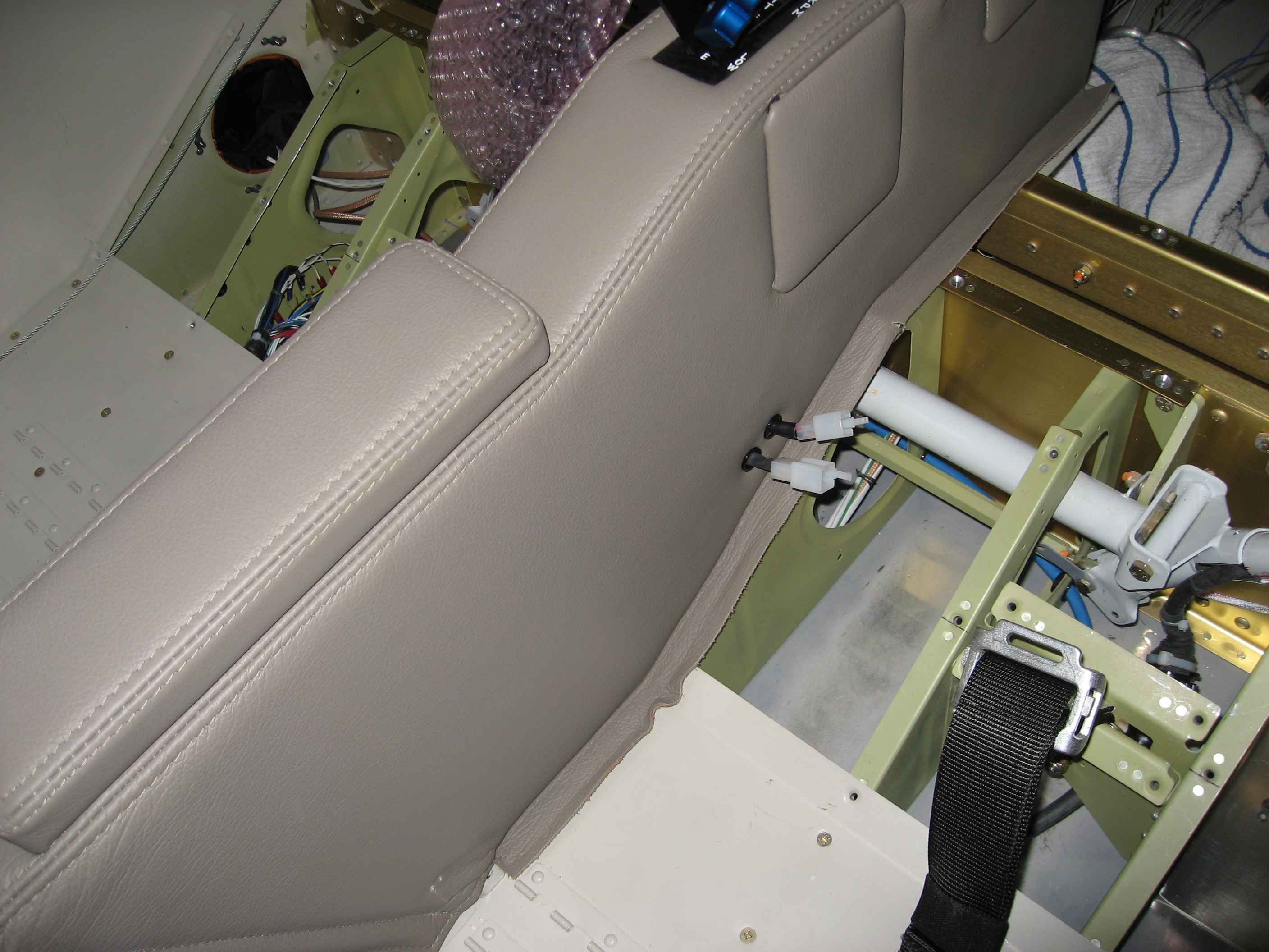
Here you can see the co-pilot seat heater
connectors coming out the side of the console. There are two connectors:
one for the seat bottom and one for the seat back.
You may have also noticed in this picture the seat belt crotch
straps are installed. Somewhere along the way I installed my
Hooker Harness system. |
 |
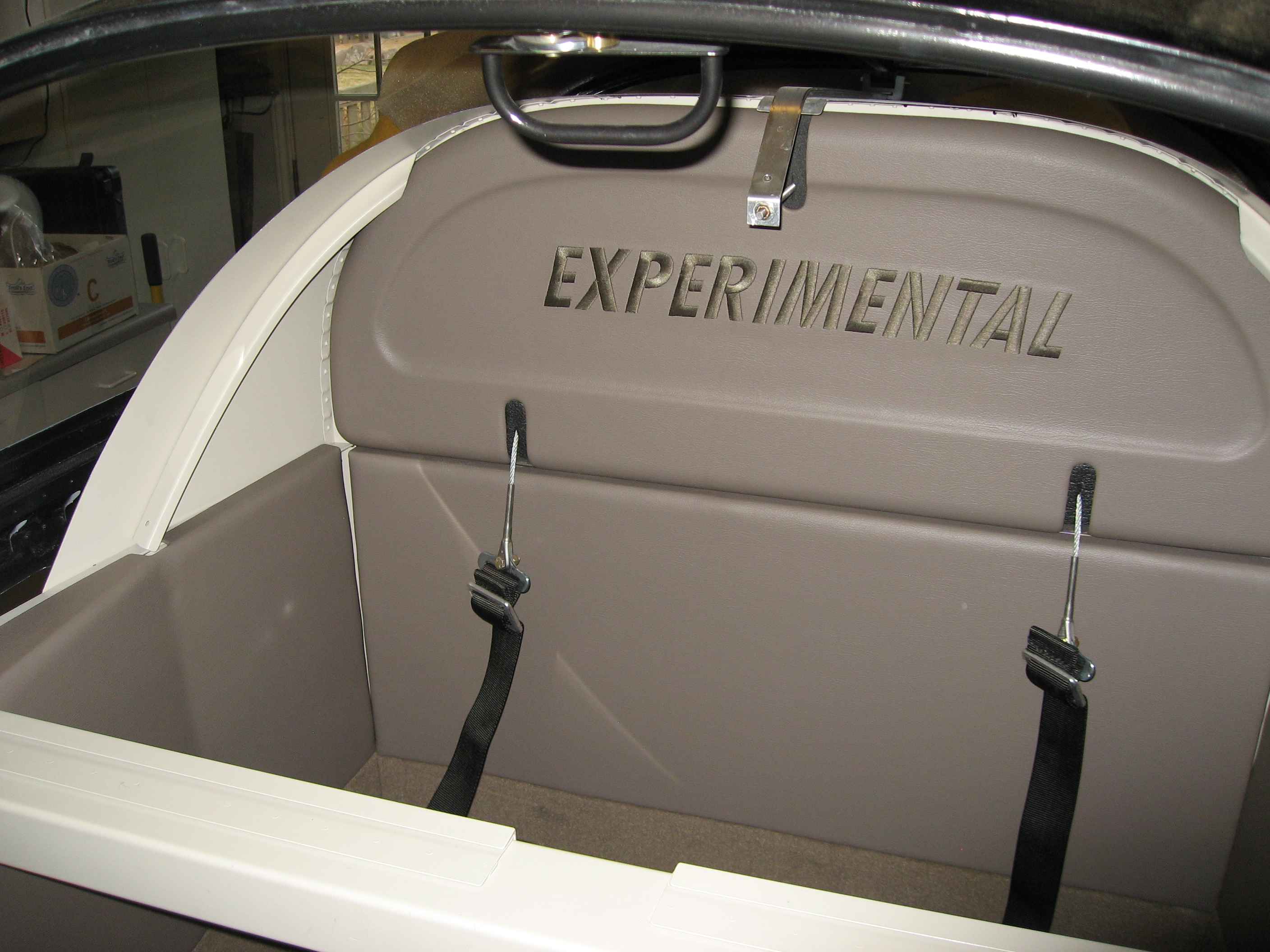
Since I had all my aft wiring complete, I
decided to close out the center section tunnel and baggage bulkhead.
I also installed the Classic Aero interior in the baggage compartment,
just to see how things fit. Pretty nice!. |
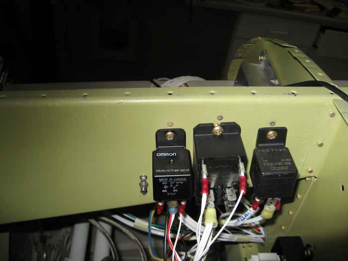 |
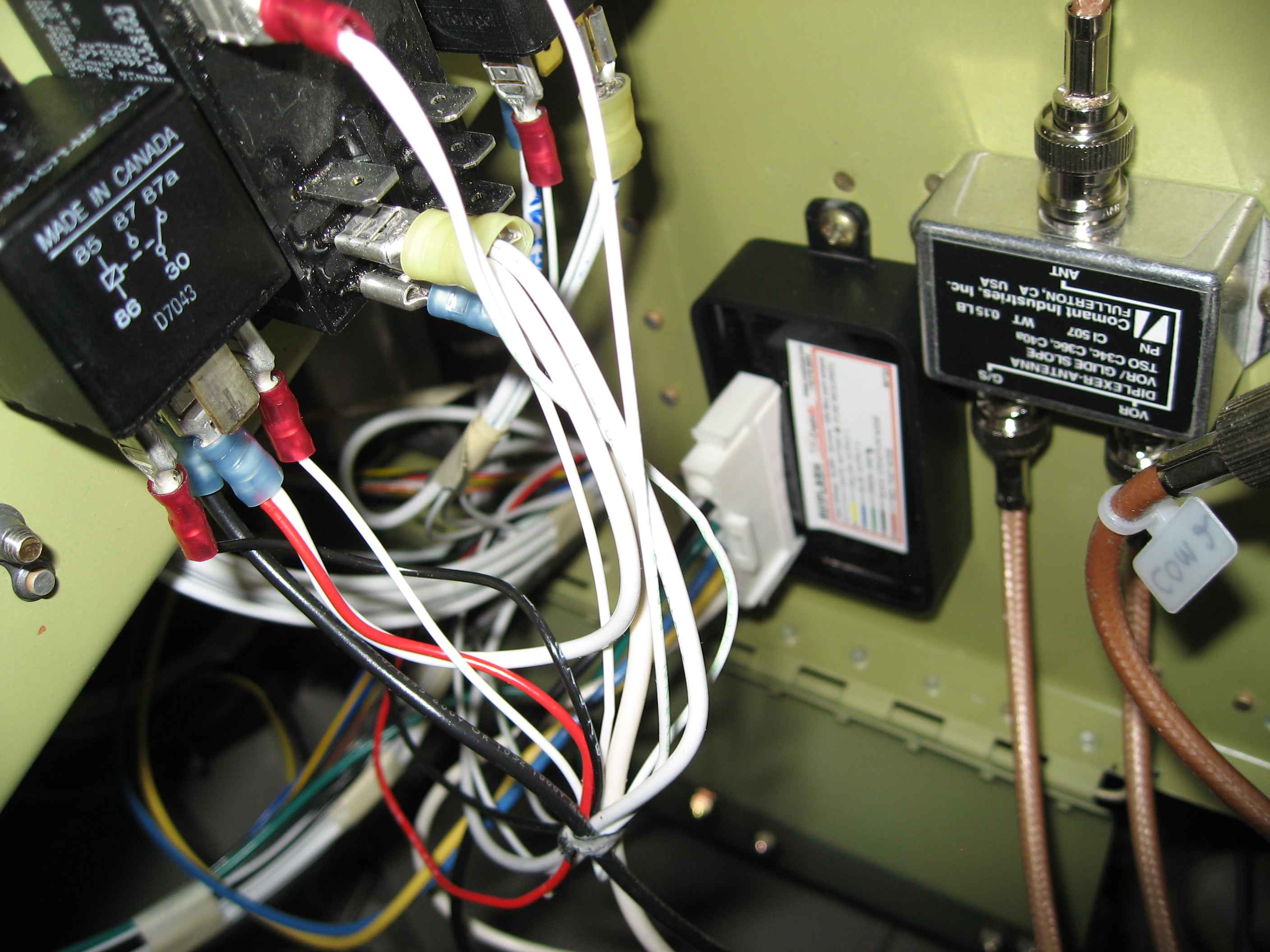
I wired up the landing light system, which
required me to use a couple of relays since I was wanting 3 functions to
work off a single rocker switch (Off- On- Wig/Wag). The two
relays on the left are for the landing lights. The one on the
right is for my Avionics Master switch. I also ran the wiring for the
Navigation lights, and pitot heat. All the wiring that goes
to the wings I have run to the outside of the fuselage and left coiled
up until I install the wings. It should be a pretty straight
forward process to pull the wires through the conduit in the wings and
connect things up when I get to that stage of the process. |
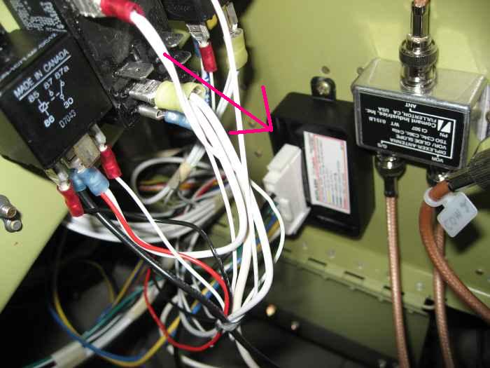 |
I think this picture was to show where I
installed my AviFlash unit which controls the Wig-Wag function for my
landing lights. This is wired into the relays and from there to
the rocker switch in the panel.
Wow, that is mess of wires!.. However, no problems.
I will bundle and lace all this stuff up shortly and it will look nice
and pretty. |
 |
So, I finally got around to scheduling a
second visit from an EAA technical advisor. The advisor from my
first visit is no longer acting in that role, so I had to find another
advisor. I checked with the local EAA Chapter (515) and found Dave
Biesemeier.
Dave looked things over and was happy with the quality of my work.
He offered to come back out right before my FAA Airworthiness inspection
to give everything a once-over. I will definitely take him up on
that offer. |
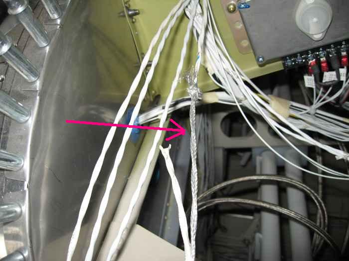 |
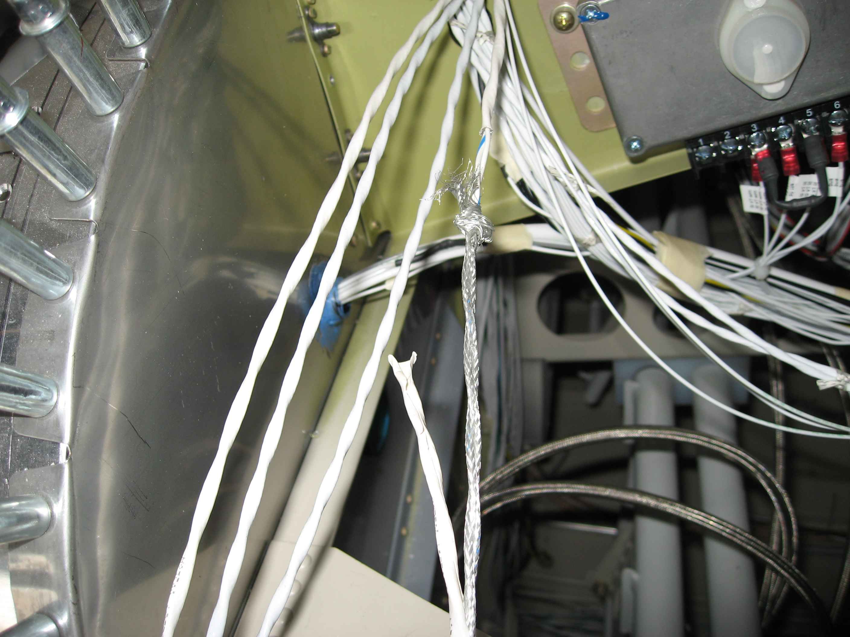
I jumped into wiring up the FADEC cabin
harness, Serial Bus Controller, and Health Status Annunciator (HSA)
unit. The issue I ran into with the pre-made harness is that
twisted pair shielded wire is used. That put each power connection
right next to each ground connection. This would not work for me.
I have my ground tree on the back of the firewall and power busses under
the sub-panel. After consulting the FADEC Yahoo Group and calling
Aerosance, I confirmed that it would not be a problem if I stripped back
the shielding and re-routing the grounding. This was kind-of a
pain, but it worked out fine
Here I am stripping back the sheathing from on of the shielded wires.
I believe there were about 10 of these wires that needed to be stripped. |
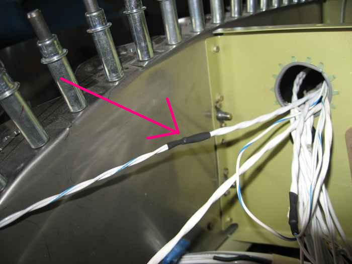 |
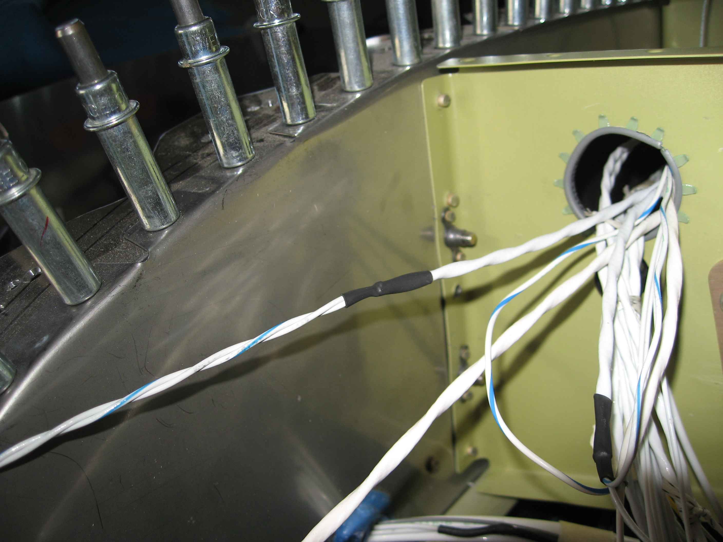
After removing the sheathing and
shielding, some shrink wrap is applied over the trimmed area to prove
some support. The twisted wires are then separated and run to
there appropriate grounding and power points. |
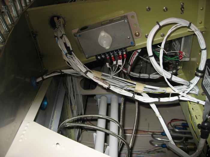 |
Here I have completed the FADEC harness
wiring on the left side of the firewall and began bundling the wires
with black waxed lacing. |
 |
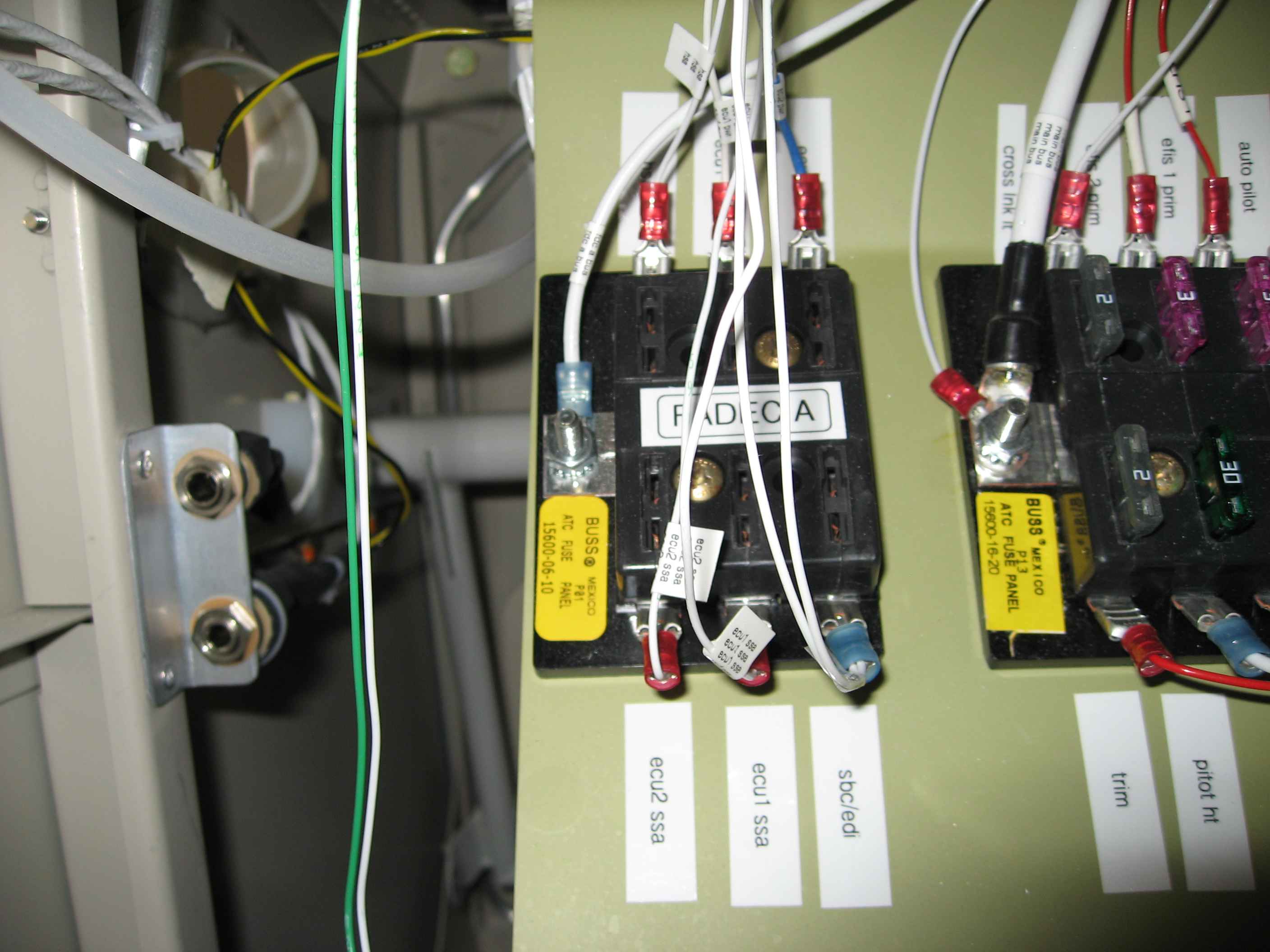
Here are a scramble of wires connecting to
the FADEC A bus. Eventually this will get laced up. |