 |
December
16, 2007 - January 5 2008:
(8.0 hrs.)
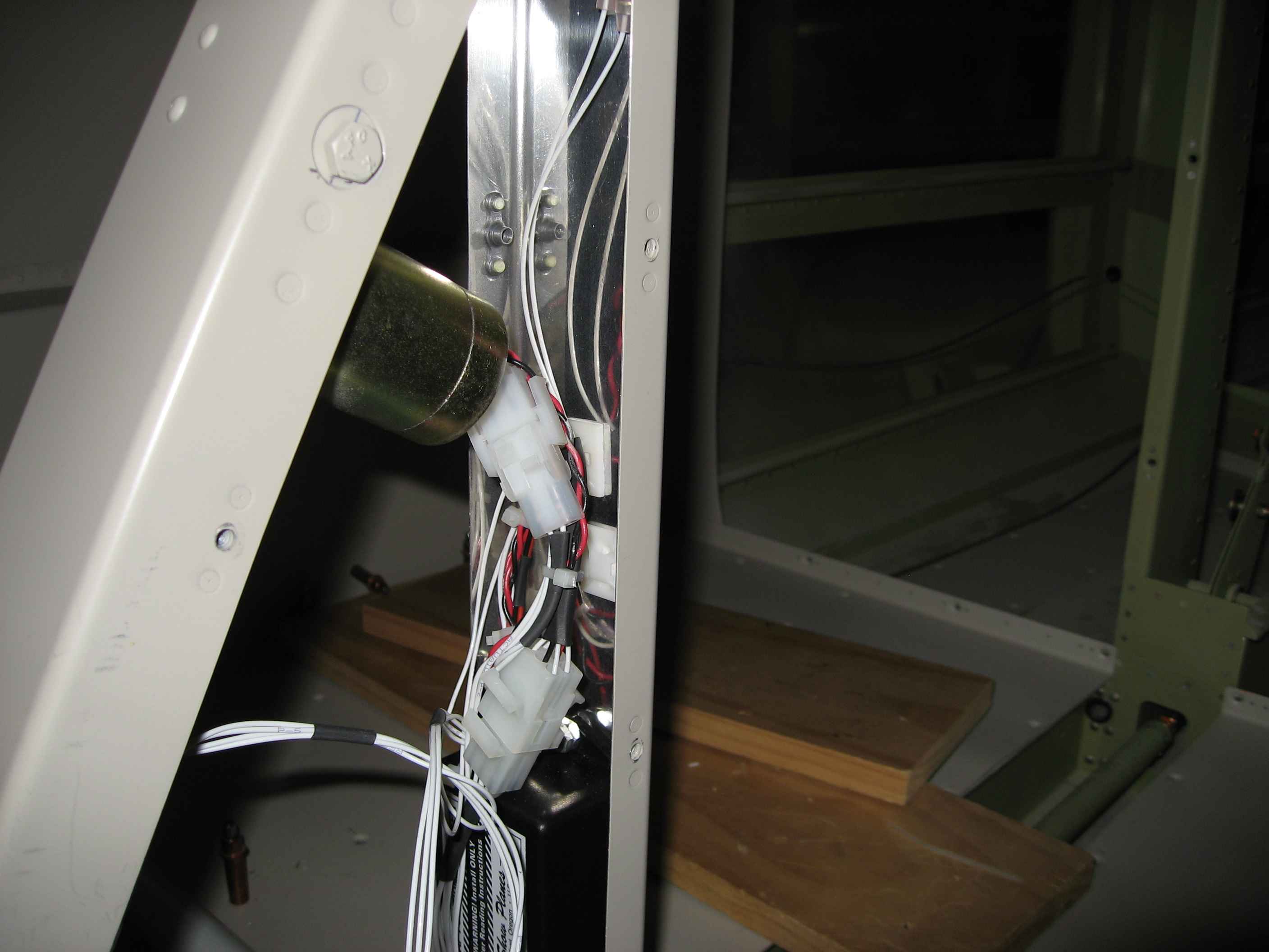
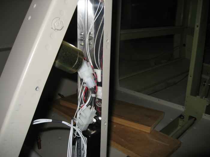
I cleaned up the wiring for the flap positioning system.
Another Molex connector was installed to house the wire connections for
both the flap system and the baggage compartment light. |
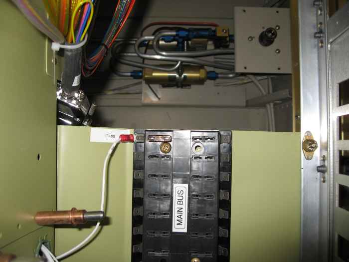 |
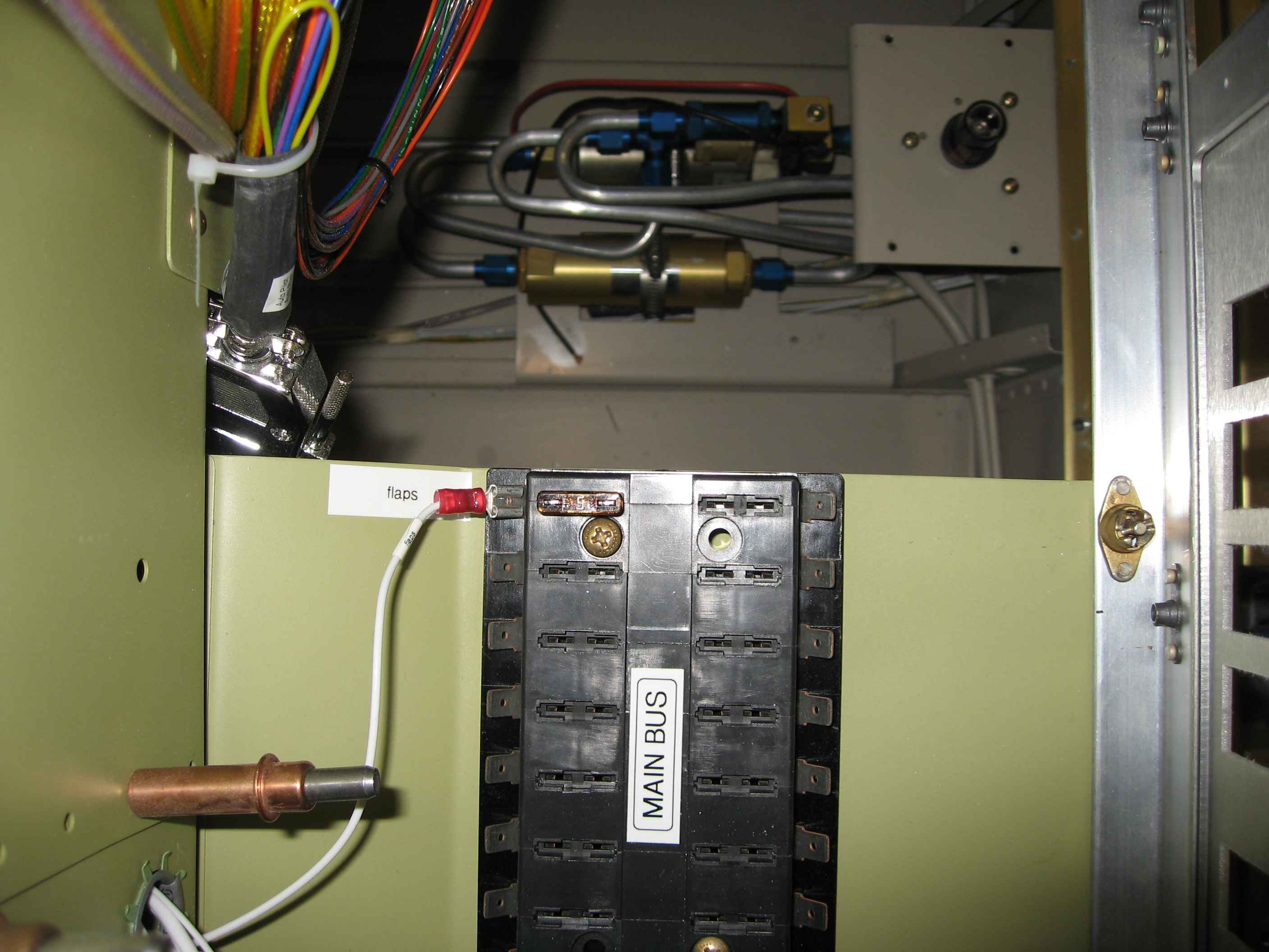
I ran the positive feed for the flap
system. This is the first item to get put into my main bus system.
I also ran the ground for the flap system to the main ground block.
I then spent some time running the flaps up and down using my stick.
Pretty cool to actually see the first system work. While I was at
it, I tested that my auxiliary battery contactor and cross-over
contactor was working. |
 |
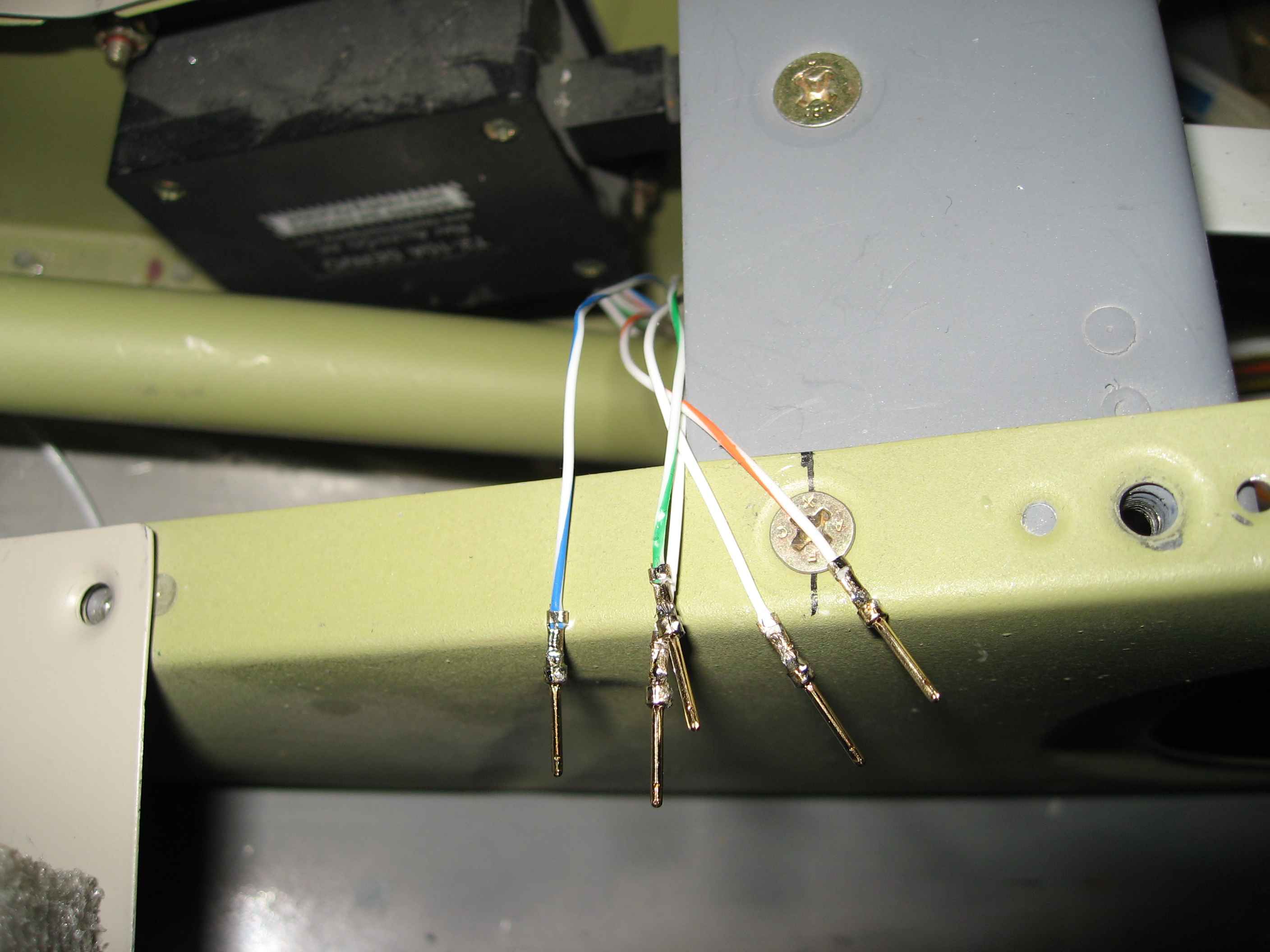
My aileron trim server has these five
small wires coming out of it. A lot of builders have had success
using a DB connector here, so that is what I am going to do. Here
I have soldered some DB connector pins onto the wires. |
 |
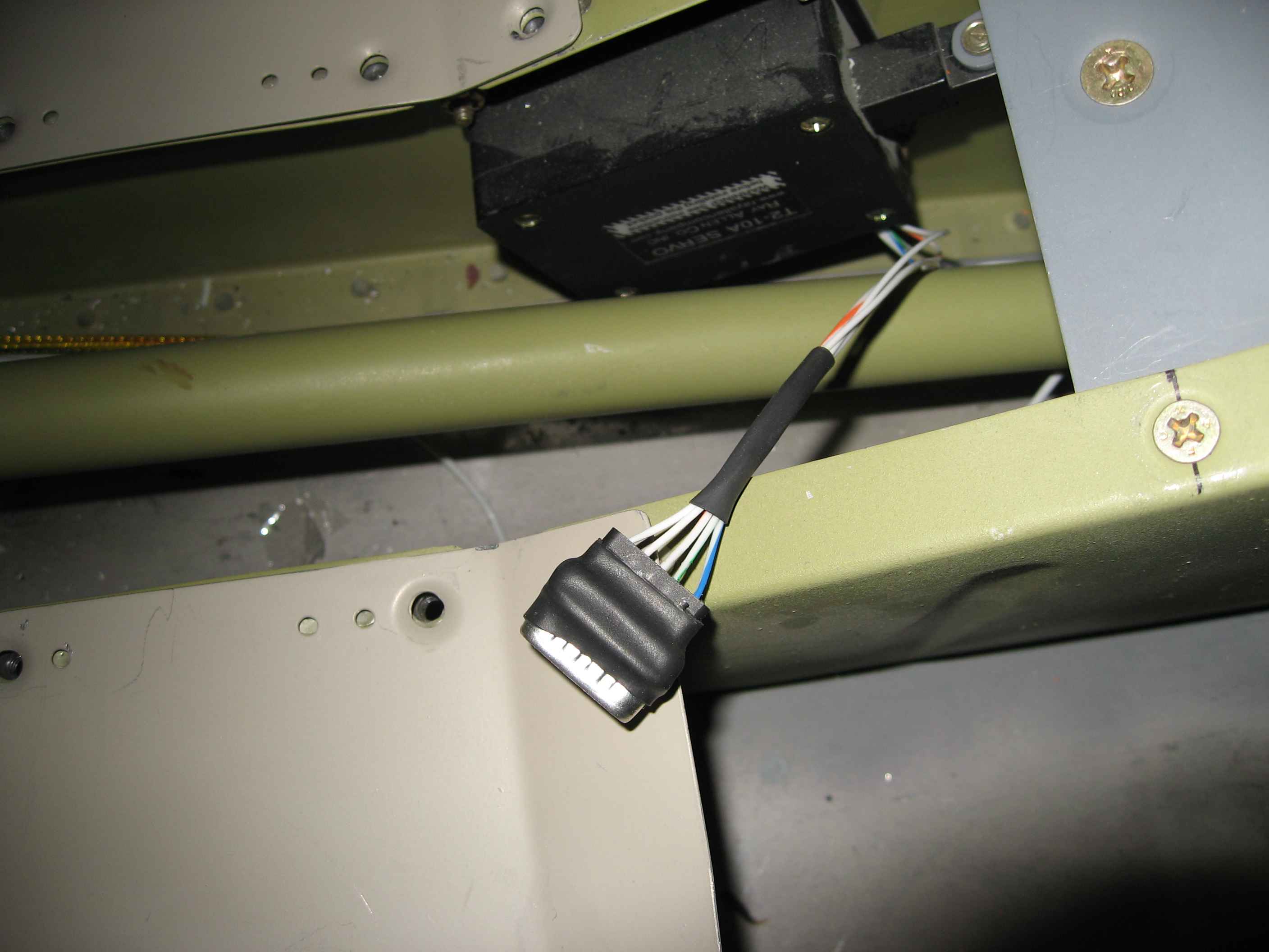
In an effort to reduce the size of the DB
9 connector, I removed its casing and then used some heat shrink to hold
the component together. Here the female DB 9 terminal has been
installed. |
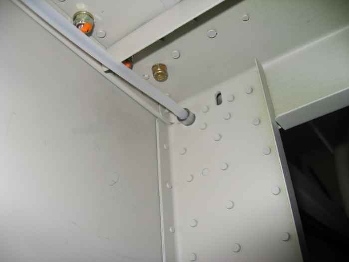 |
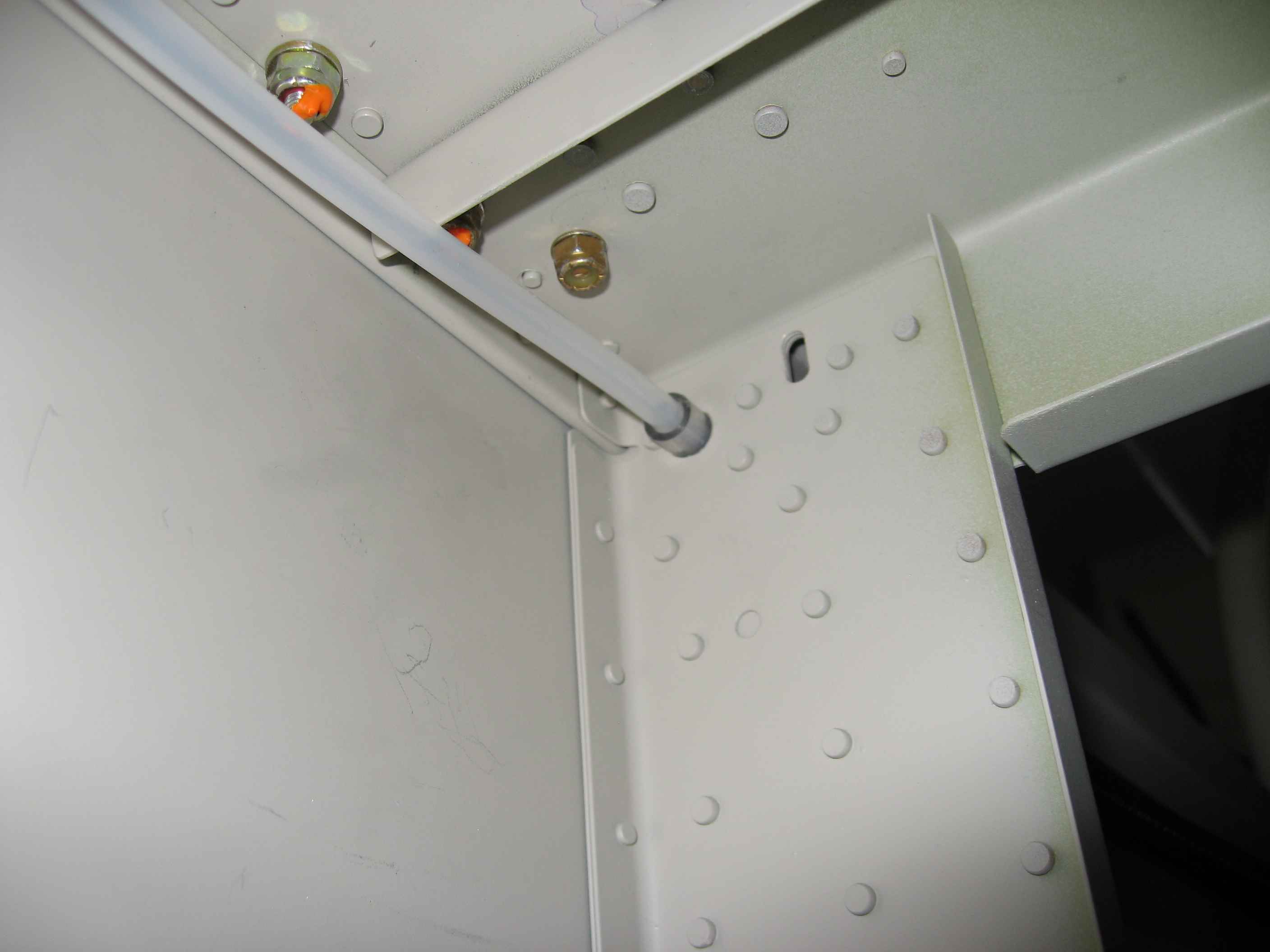
Finally got around to running the static
line up to the panel. There are holes and grommets in all the
bulkheads for this run, except for the seat back bulk-head. I just
drilled my own hole. Because this bulkhead is so thick, the
standard plastic grommets wont fit. I ended up using some plastic
tubing in place of a grommet. |
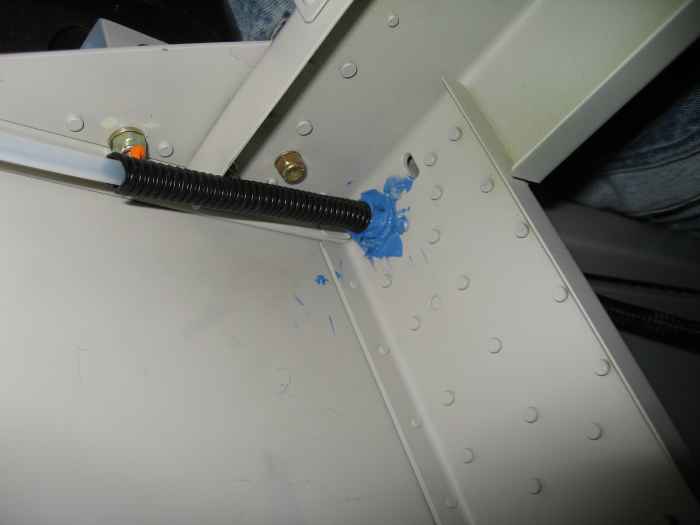 |
I also added some RTV (the blue stuff), to
make sure the tubing stayed in place. Yes, I was messy with the
RTV, but it wont be seen in this location. The black stuff is some
wire conduit tubing. I added a bit of this to this area to keep
the static line from chafing on the flange located on the bottom of the
seat back bulkhead cross member. I also used this tubing in the
area where the static line runs underneath the canopy deck. |
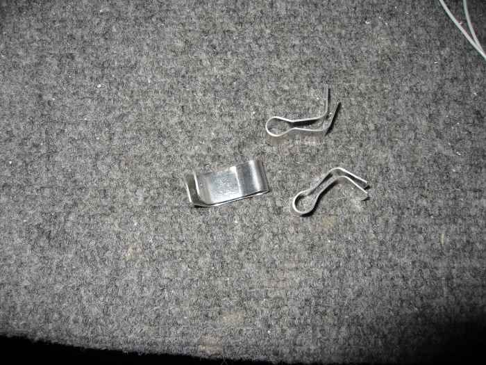 |
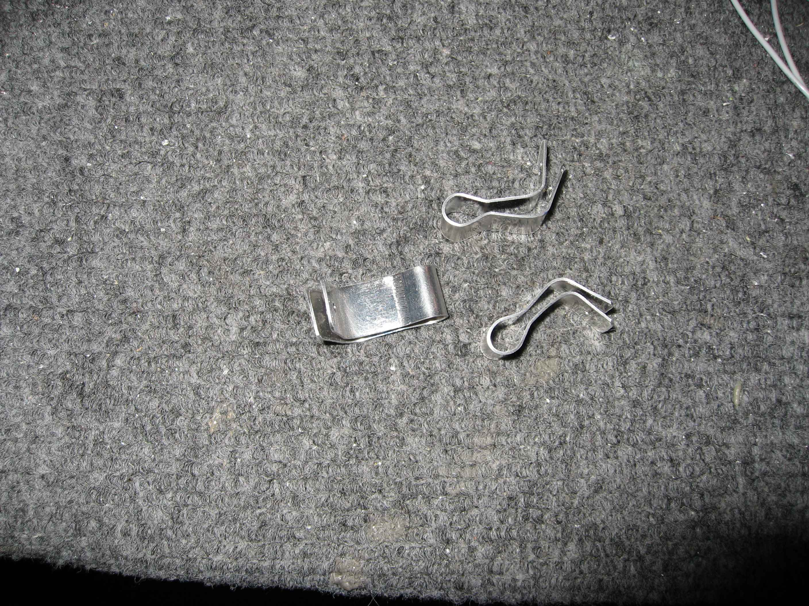
Created these aluminum clips to help hold
the static line sturdy behind the baggage compartment bulkhead.
The get riveted to the longeron using one of the many places where the
sides skins attach. |
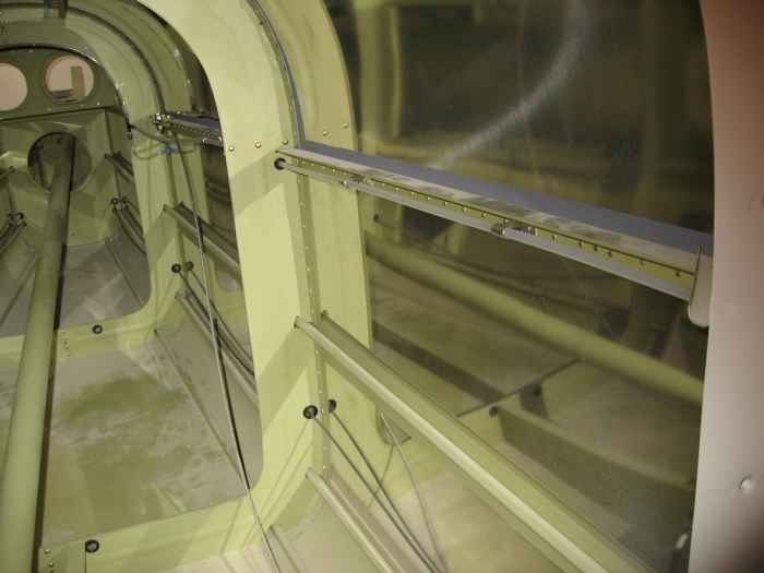 |
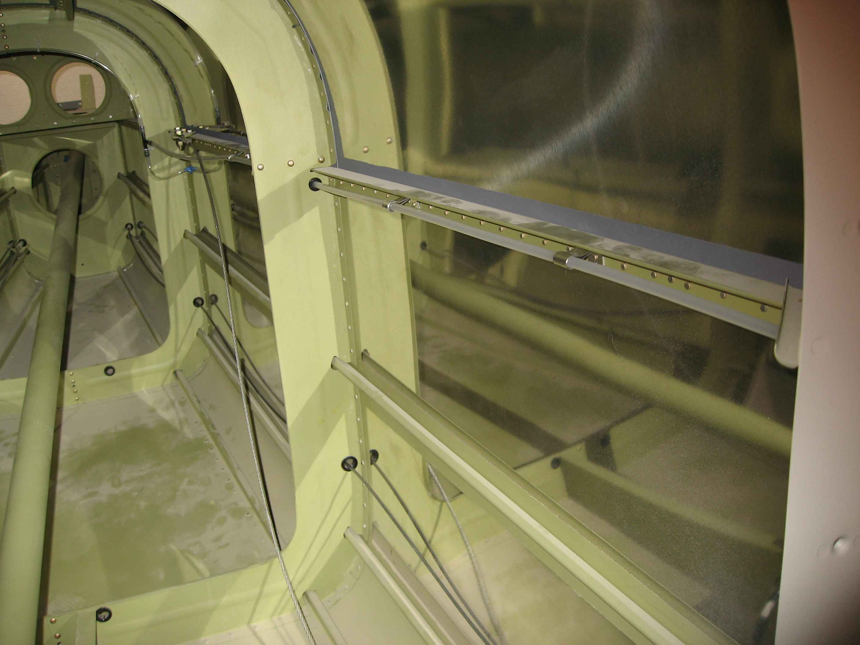
Here is a picture of the static line
running along the longeron and held in place with my clips. |
 |
January 11-13 2008:
(4.0 hrs.)
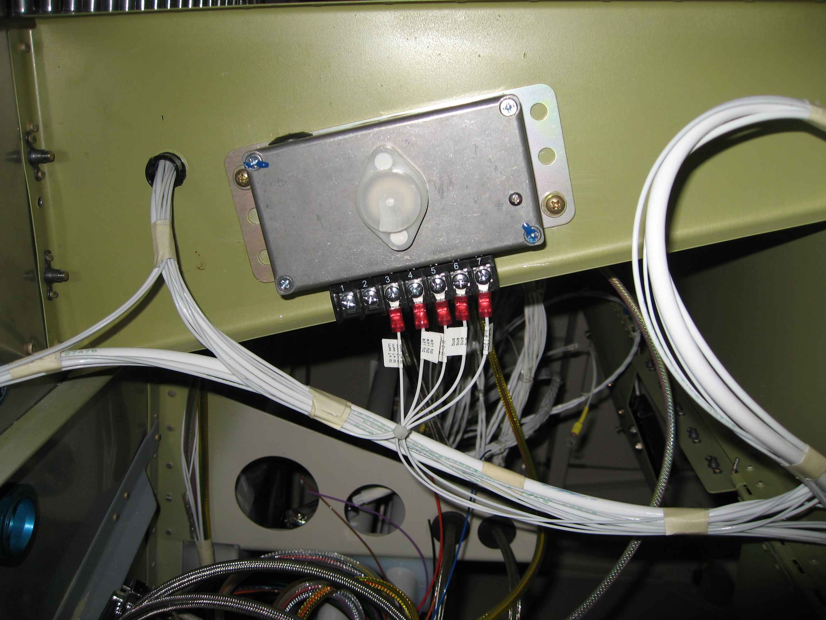
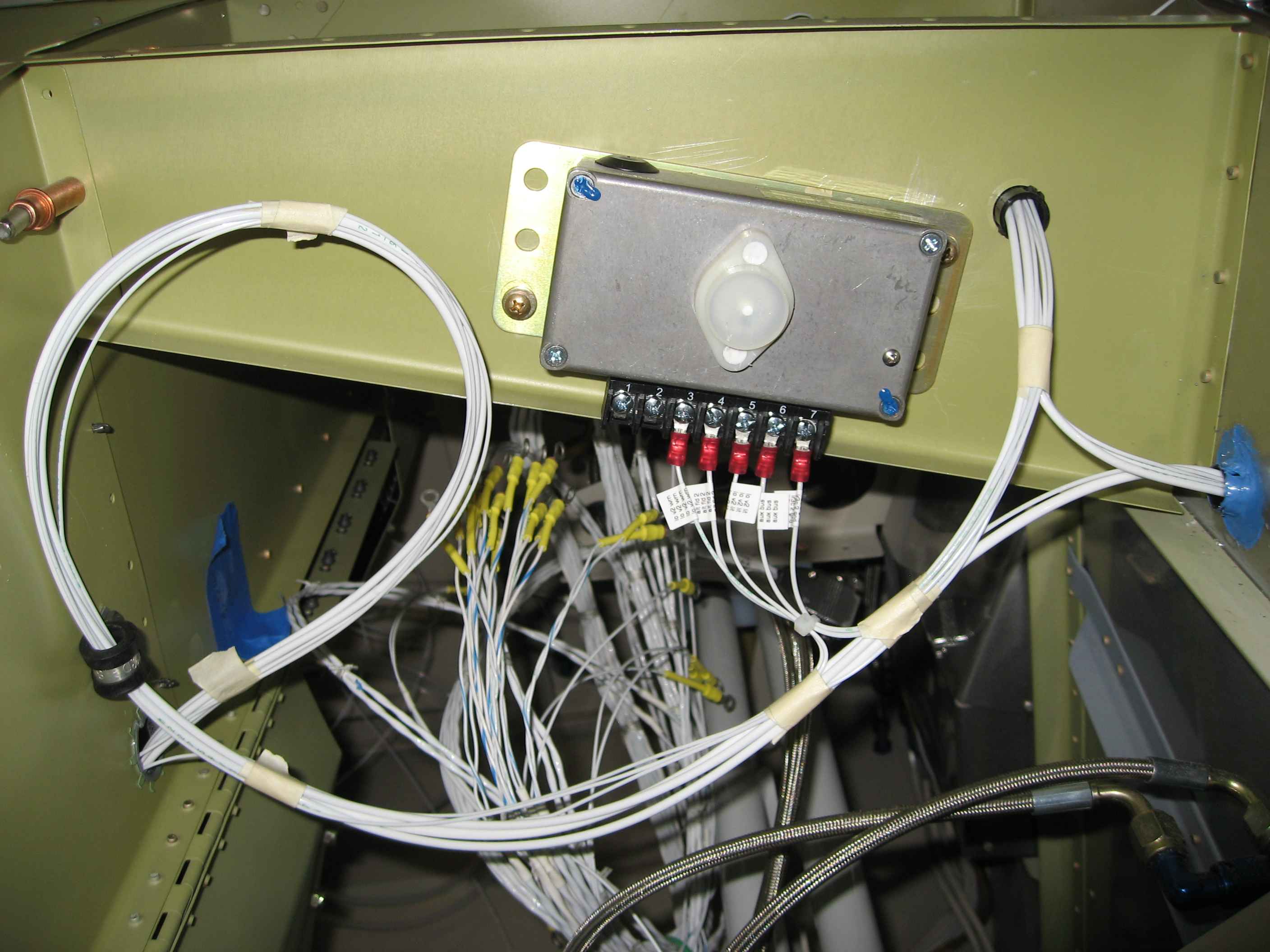
I wired up the alternator regulator. This involved running the
field wire to the alternator, a ground line to the ground block on the
firewall, a line to the bus, an over-voltage warning line, and an
over-voltage light line. The other two terminal locations are for
an optional battery temperature sensor. |
 |
Here is the other alternator also wired
up. |
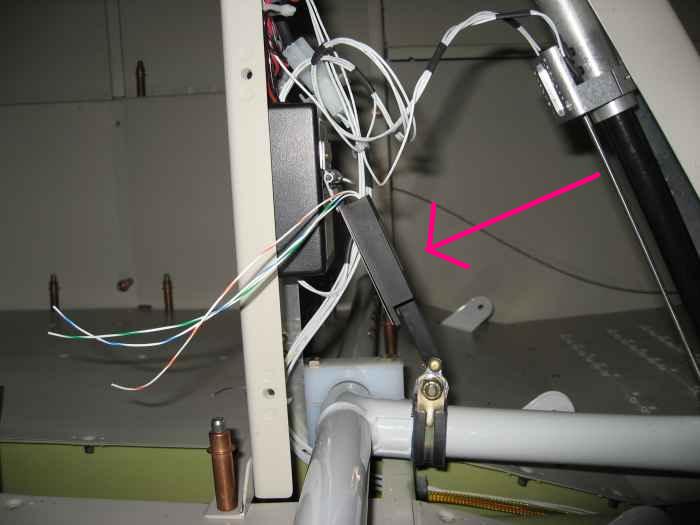 |
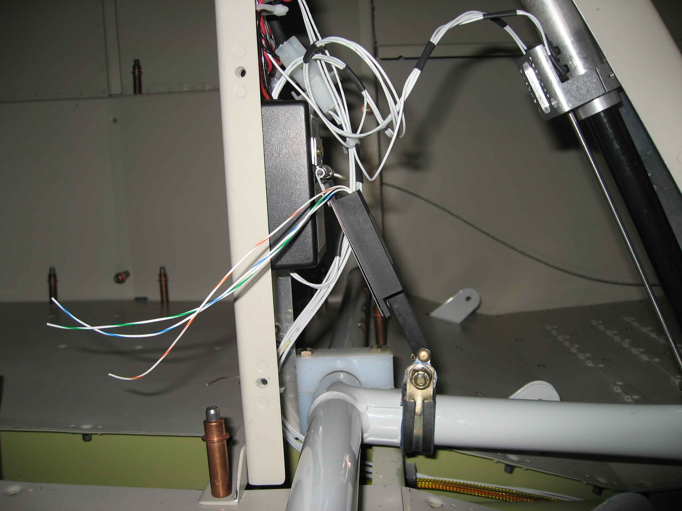
I ordered this positioning sensor unit
from Ray Allen (POS-12). It is basically a linear potentiometer.
It will send a flap position signal to the EFIS. I spent way too
much time on install this, but I think it turned out quite nice.
The top edge is hinged and attached to the cover case for the FPS unit
from Show Planes. The bottom end is attached an Adel Clamp on the
flap mechanism. |