 |
April 25-27, 2008:
(8.0 hrs.)
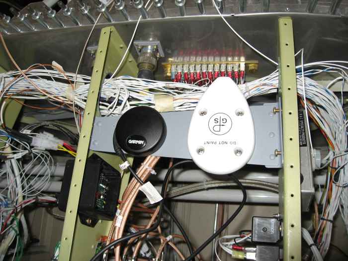
Built this tray to hold my GPS antennas on the top deck. I will
have fiberglass access panels above these, so they should have no
problem with satellite reception. I also made this tray removable,
so if I have to, I can get to stuff below it.
Yes, the GNS 430W antenna is backwards.. I don't know why, but I just
bolted it on that way. I don't think it really matters which
direction it faces unless it is external to the aircraft, then
aerodynamics would be the reason.
See that big mess of wires! My next job is to clean that up.
|
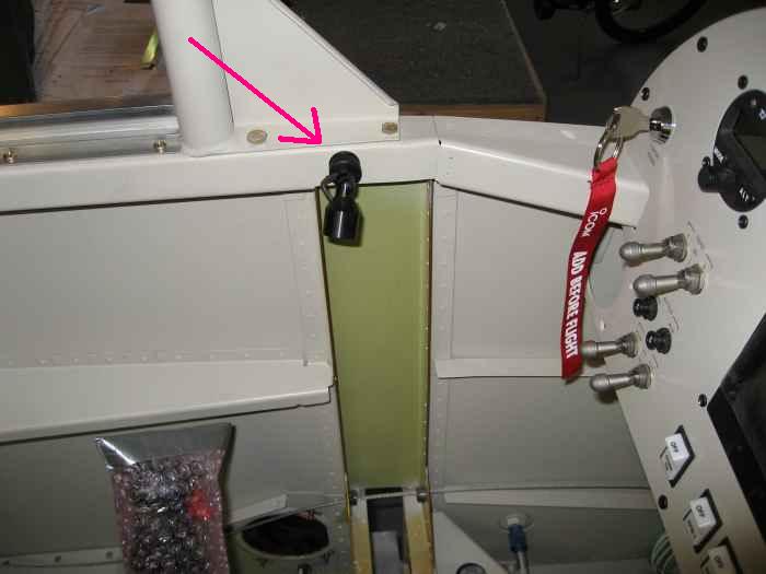 |
Well, one more minor task before cleaning
up the wiring. I wanted to mount a small LED map light on the
pilot side. I mounted it up on the forward canopy deck. This
unit is adjustable, so I can point it any which way. |
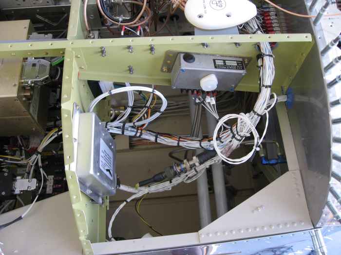 |
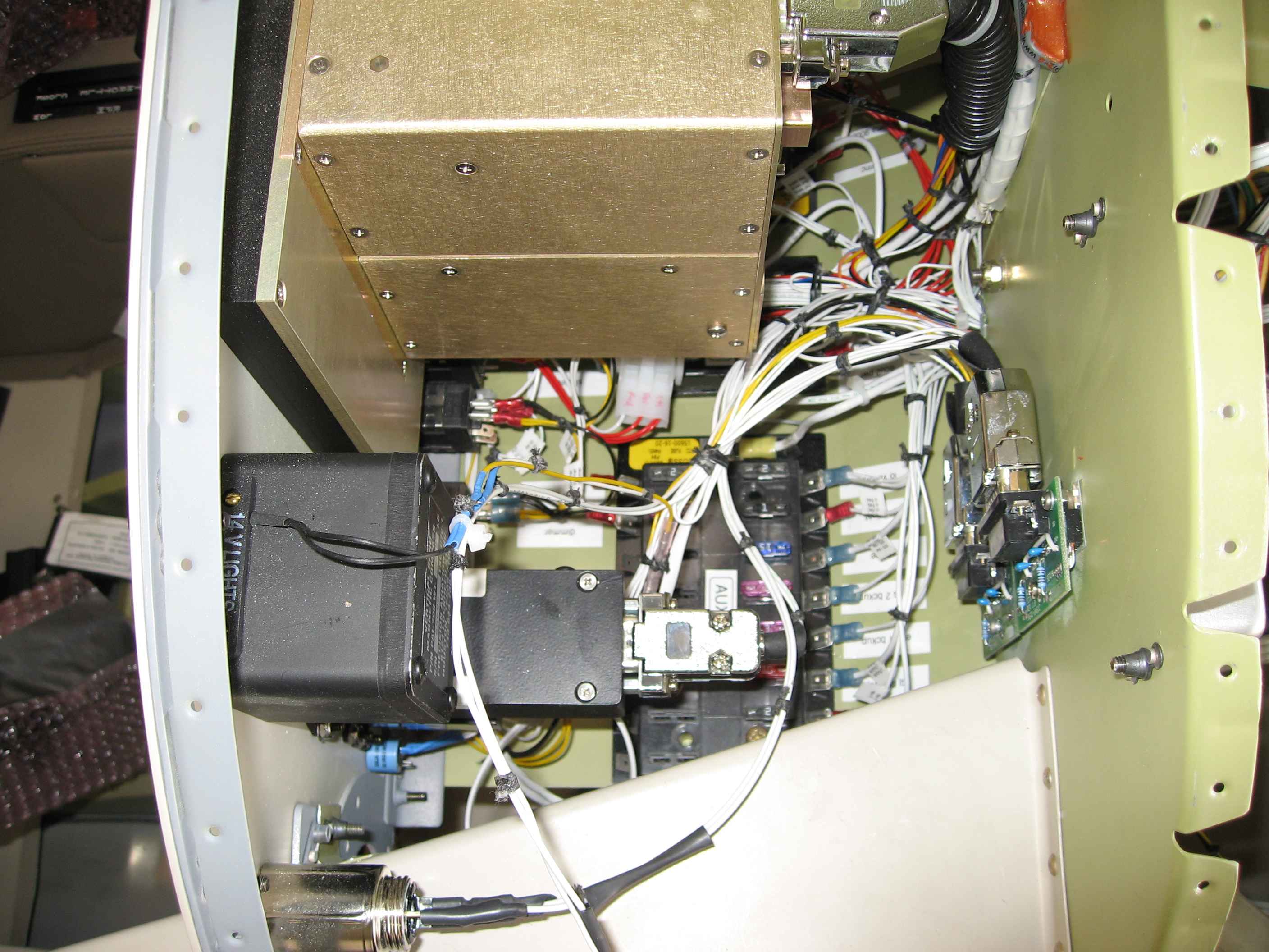
OK. The map light made up the last
bit of wiring (I hope), so now on to making things tidy. This
might not look like much, but I spent a good 5 hours lacing up all my
wiring. Some places are very difficult to reach with two hands to
tie knots in the black lacing cord.
Here is the front right side wiring nice and clean. Oh, one
other thing I did that I do not have a picture of, is I mounted the DB9
connector for the FADEC serial bus. I put it right below the
passenger side stearo and mic jacks. I will use this to get health
information from my FADEC system into my laptop computer for
diagnostics. |
 |
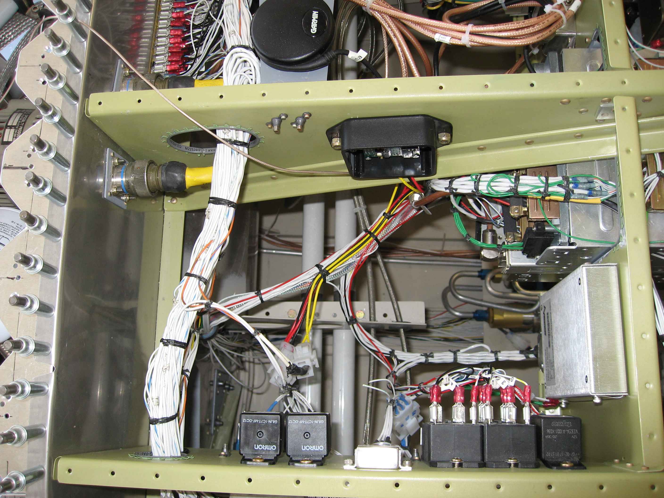
Right side behind the panel with the fuse
bus tray in the closed position. This is a tight fit, but should
work out.
That one extra set of wires hanging out the bottom of the picture is
for the LED light strip that will go underneath the glare shield.
I can't connect that until I have the top skin riveted on... and that
wont be for quite awhile. I want to leave this open as long as
possible. |
 |
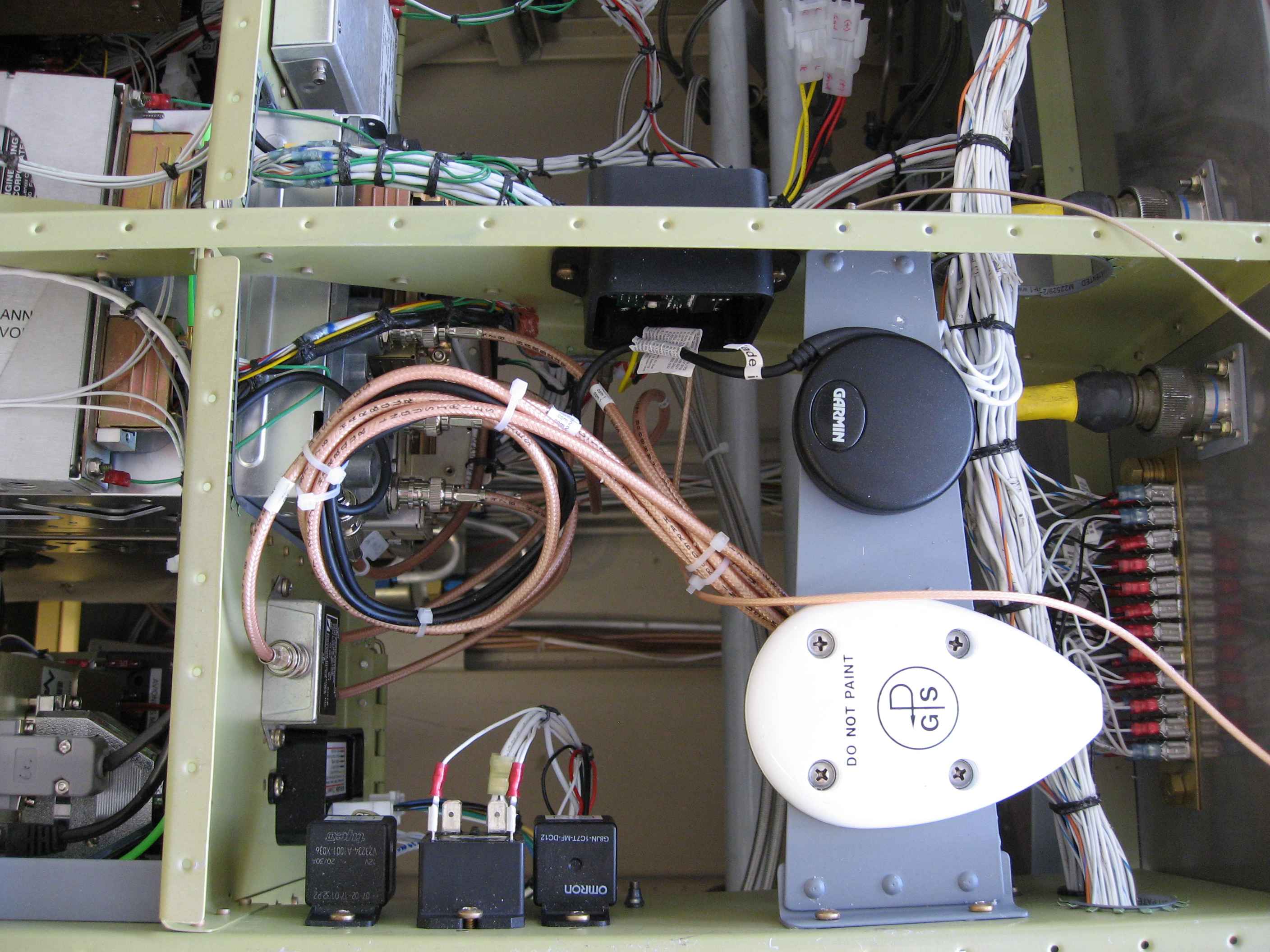
Front right center. |
 |
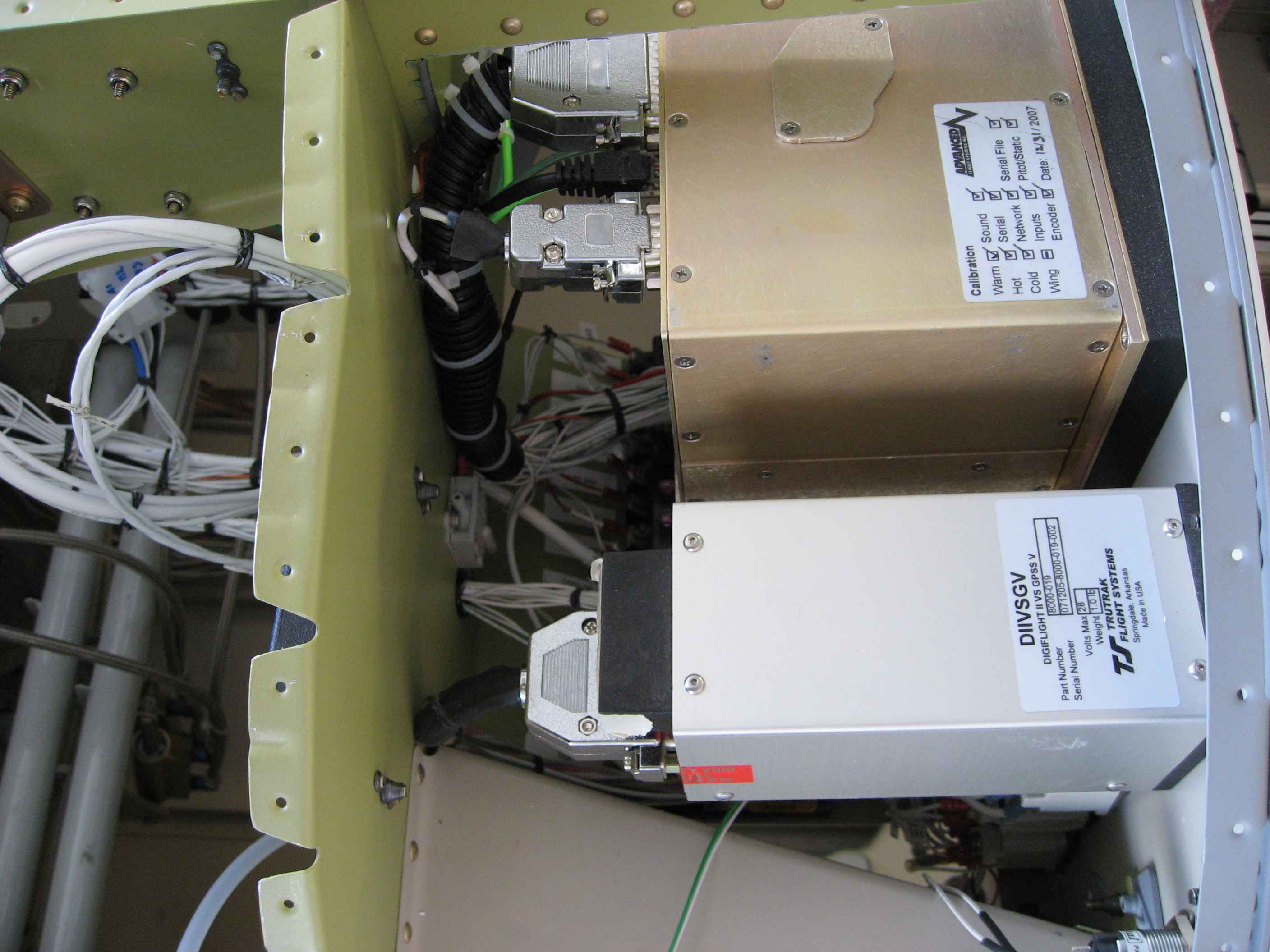
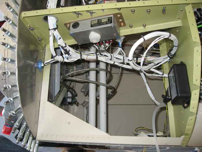
This is another shot of the right side
behind the panel. Notice there is very little room between the
back of the EFIS system and the sub panel. The harness for the
EFIS system is touching the sub-panel. I was worried about
chaffing, so I added the black protective wire cover |
 |
Front left center. |
 |
Front left |
 |
And finally, behind the left side of the
panel. Here too, I added some protective wire cover to the EFIS
harness. I ended up also putting some on the auto pilot harness. |
 |
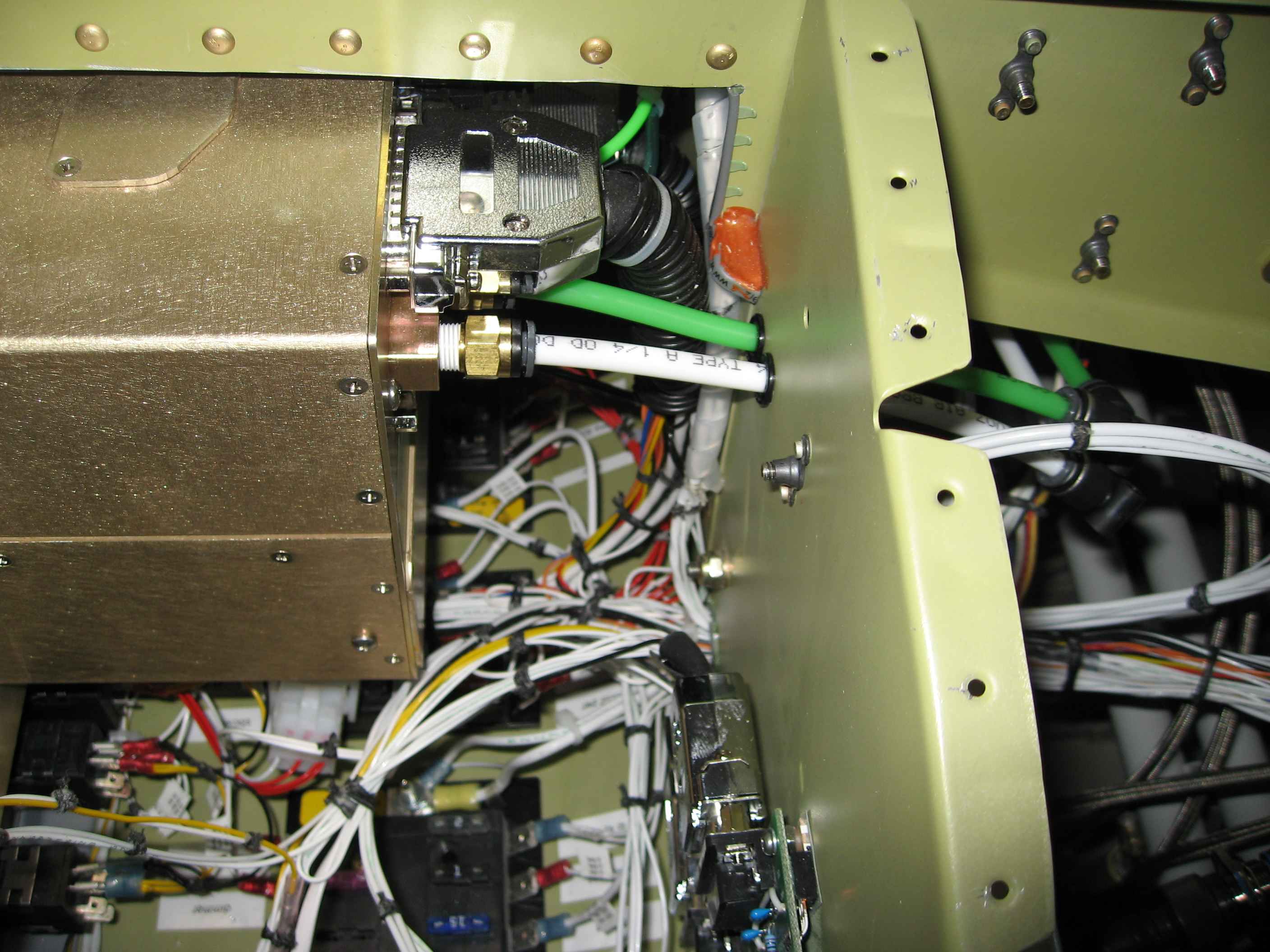
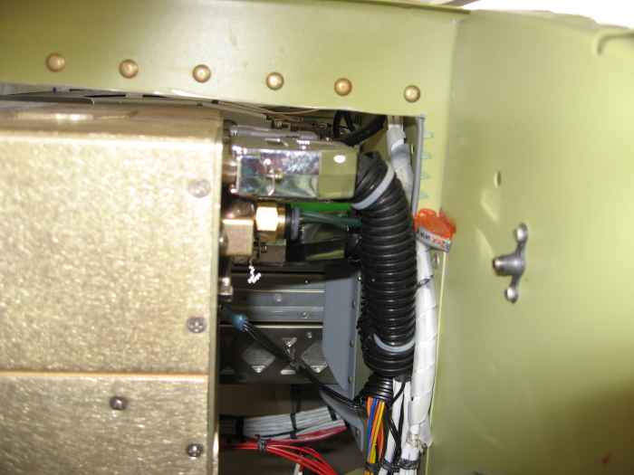
Next I moved onto plumbing the static and
pitot lines to the instruments. Since there was not much room
between the back of the instruments and the sub-panel, I decided to run
the plumbing on the front side of the sub-panel.
This is behind the passenger side EFIS system. I ran the static
(white) and pitot (green) lines through some grommets I drilled for in
the sub-panel. I also used special quick connect fitting from
SafeAir1. These are really nice and easy to use. They are
smaller than the typically plumbing connectors, which is nice when you
are working in tight quarters.
|
 |
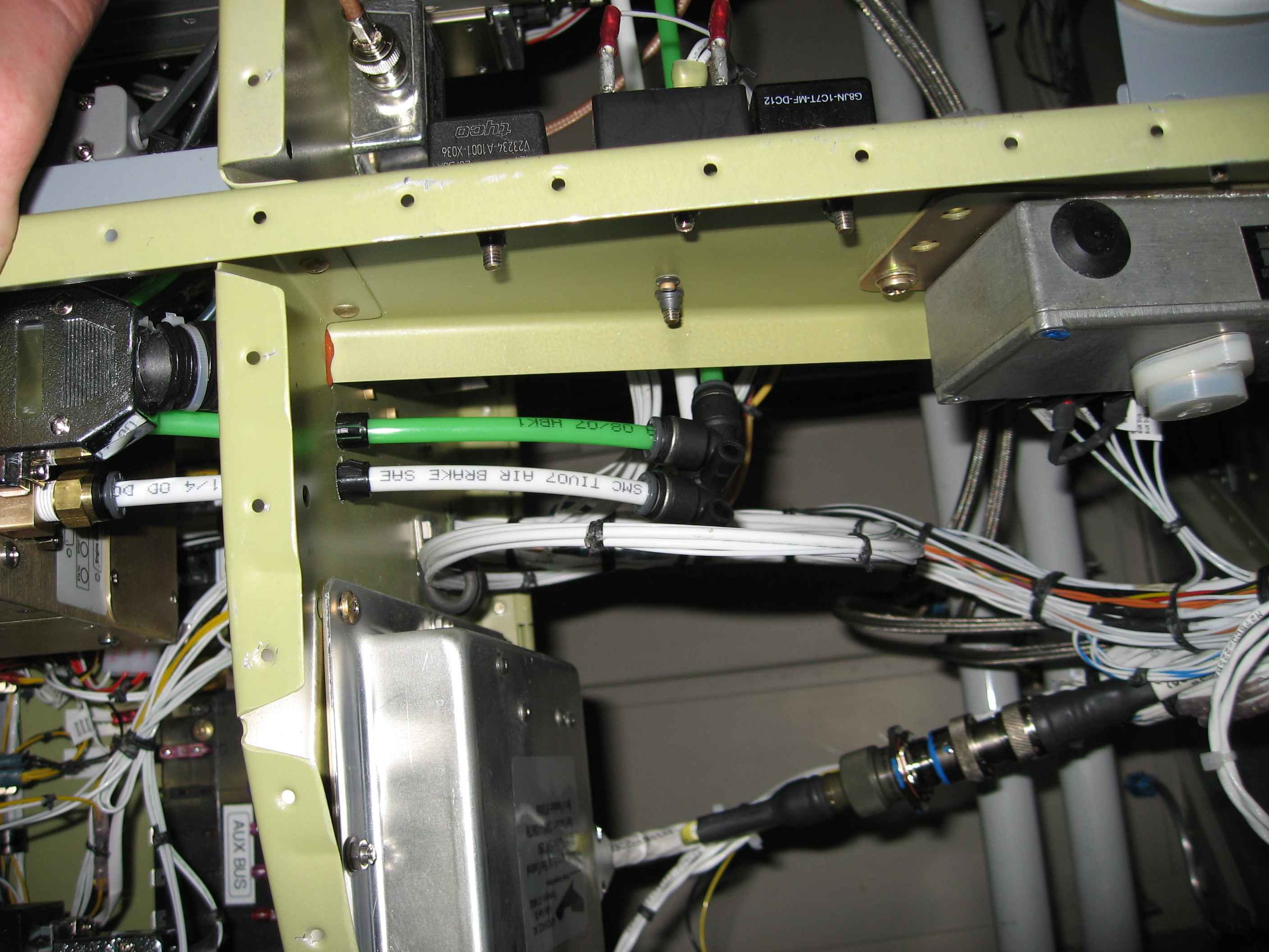
The tubes extend out a bit into the area
in front of the sub-panel and then connect into an elbow. |
 |
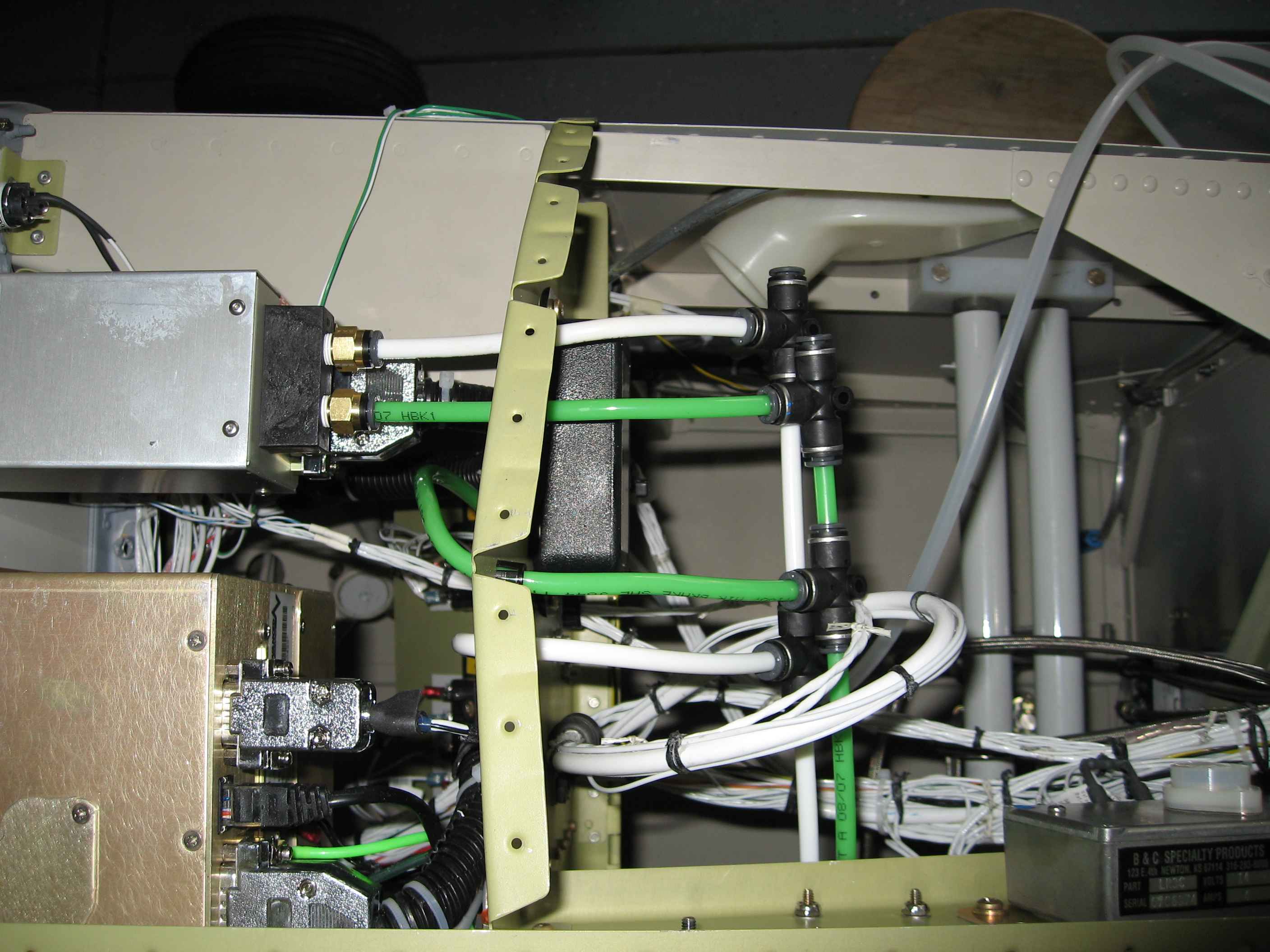
The lines then run behind the radio stack
and tee into the pilot side EFIS, flap/trim speed switch, and auto
pilot. |