 |
January 23, 2005: (2.0
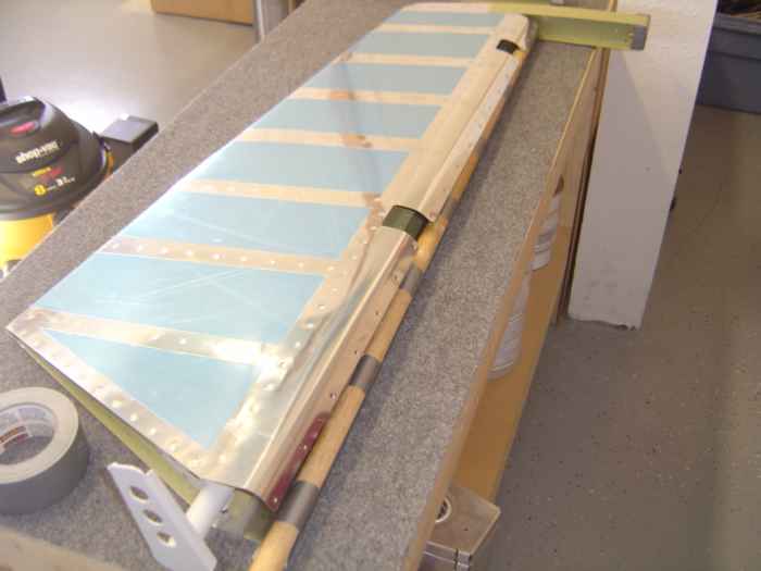
hrs.) Got out the broom stick and duct tape to roll the
leading edge of the elevators. I find this to be one of the more
difficult tasks of building this plane. The first roll usually
goes well, but then when you roll the second side of the skin, you have
to deal with the side you just rolled being in the way. You really
have to work the skin to get a good fit. |
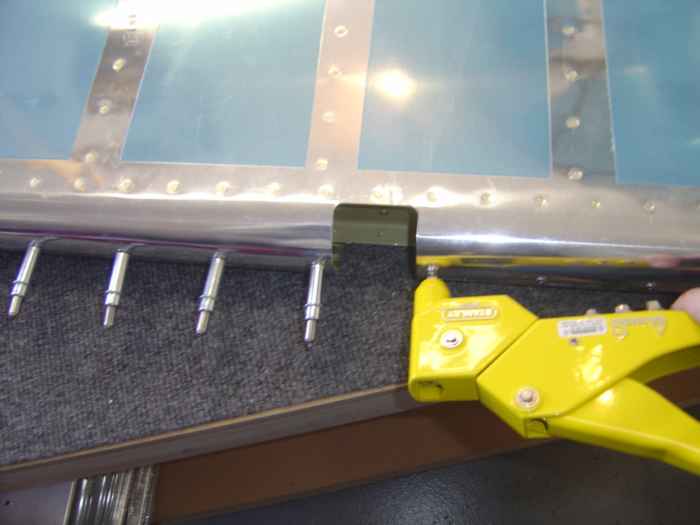 |
Finally, the edges are rolled and I can
rivet the leading edge together. Yes, those are the silver #40
cleco's... but I drill the holes out to a #30 prior to blind riveting. |
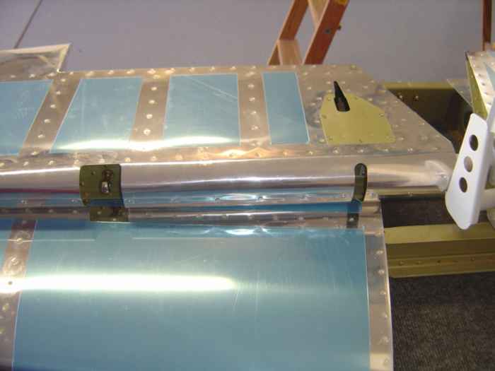 |
Here is the left elevator laying on top of
the horizontal stabilizer with the leading edge completed.
Next I will need to fit the elevators onto the horizontal stabilizer
and check for proper balance, clearance, and movement. |
 |
January 30, 2005: (2.5
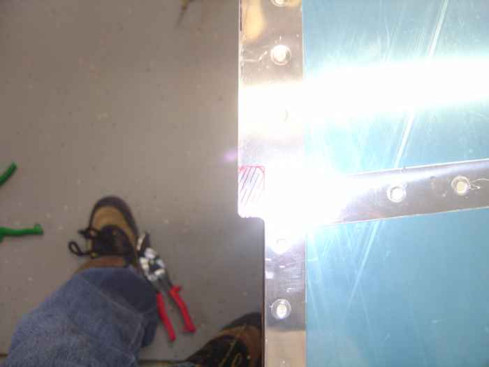
hrs.) When the elevators are attached to the horizontal stabilizer,
the outboard skins interfere with the counter balance weight. The
skins need to be trimmed to allow the counter balance to swing freely.
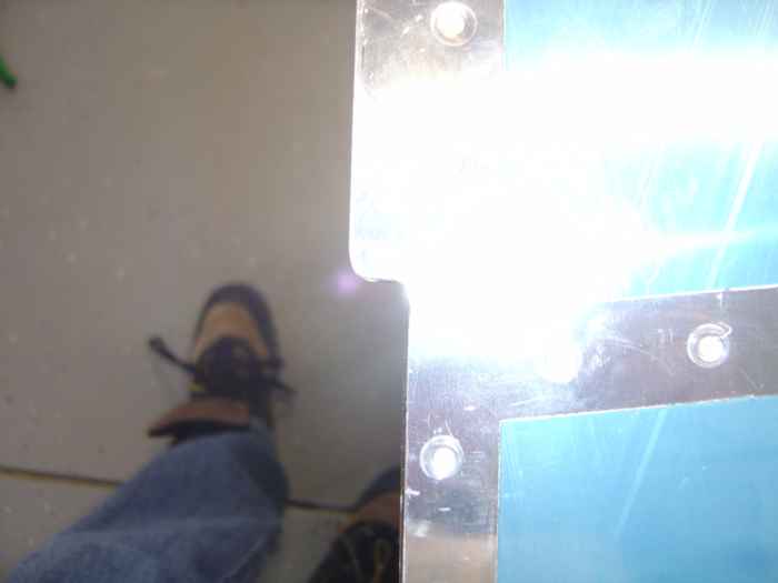
Here I have marked where the top HS skin needs to
be trimmed. This needs to be done on the top and bottom skins for
both the left and right elevator. |
 |
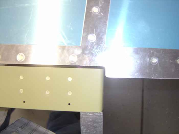
This is the final result of the cut after
rounding the corners and deburring the edges. |
 |
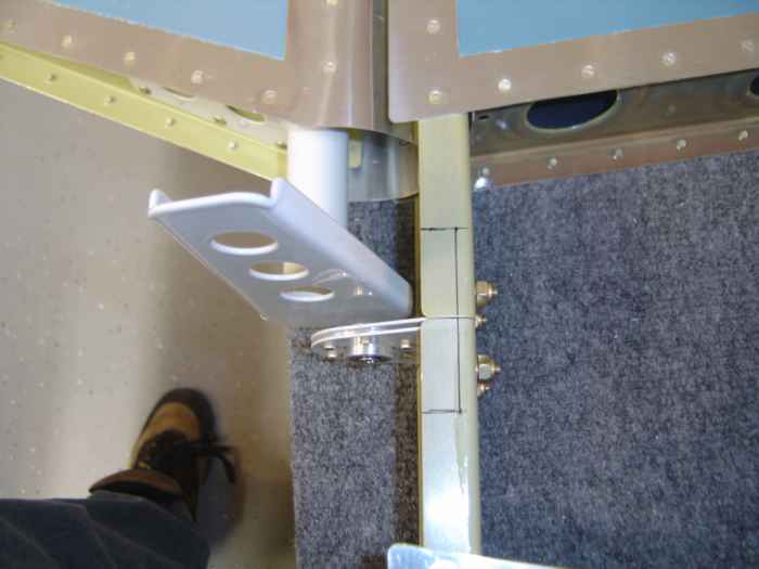
This picture shows the left elevator
attached to the HS. The counter balance weight now has room to
travel freely. |
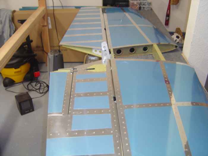 |
Next I attached the elevators and checked
for movement and balance. Everything fit and moved nicely.
The elevators are balanced a bit heavy, but I will not worry about that
until after paint.
I spend some time today hooking up the linkage of the trim tab servo
to the trim tab. I had to shave away a bit of the trim tab opening
to keep the clevis from rubbing the skin. Next, I tested the trim
tab movement by hooking the servo up to the battery from my rechargeable
drill. It was pretty cool seeing parts moving for the first time.
I am almost done with these elevators. I just need to drill and
bolt the elevators through the center bearing. Hopefully I can get
that done tomorrow and then I can start concentrating on the wings |
 |
January 31, 2005: (1.5
hrs.) Tonight I was resolved to finish up the empennage because I
am anxious to start on my wings.
To allow adequate down elevator throw, the rear
spar flange needs to be trimmed. Here you can see that I have marked
where I want to cut. You need to be careful not to cut the rear
spar reinforcements. |
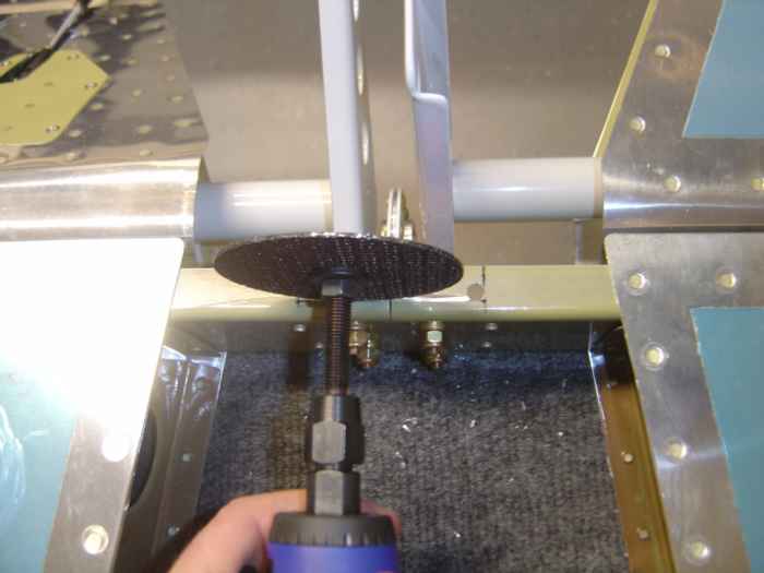 |
I tackled the this job by first drilling
holes in the corners of the area to be removed. This facilitates
the radiused inside edge of the finished cut. Next I used my die
grinder with a cut-off wheel to "carefully" cut through the spar flange.
The spar reinforcements are just beneath the flange so you need to
cut very slowly and make sure to not cut too deep. It would have
been nice if the plans and instructions called for this cut-out before
the horizontal stabilizer was assembled. Oh well, the cut was
fairly easy. |
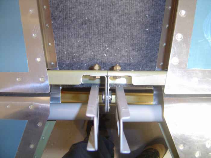 |
Here is the finished product. Not a
nick on the rear spar reinforcement plate or center bearing support. |
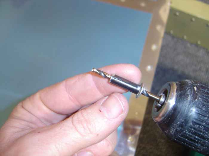 |
The elevator control horns need to be
drilled to accept the bolt that attaches them the center bearing.
The instructions call for using a drill bushing with a 1/4" OD and 3/32"
ID to be used on a #40 drill bit that is then inserted through the
center bearing to drill each control horn. I had this wall anchor
that was close to both dimensions. I wrapped a little electrical
tape on the outside to snug up its fit in the center bearing and then
opted for using a #30 drill bit. This worked out well. |
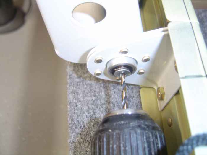 |
Here the drill bushing is inserted into
the center bearing and I am drilling the right control horn with the #30
drill bit. The same process is used from the opposite side to
drill the left control horn. |
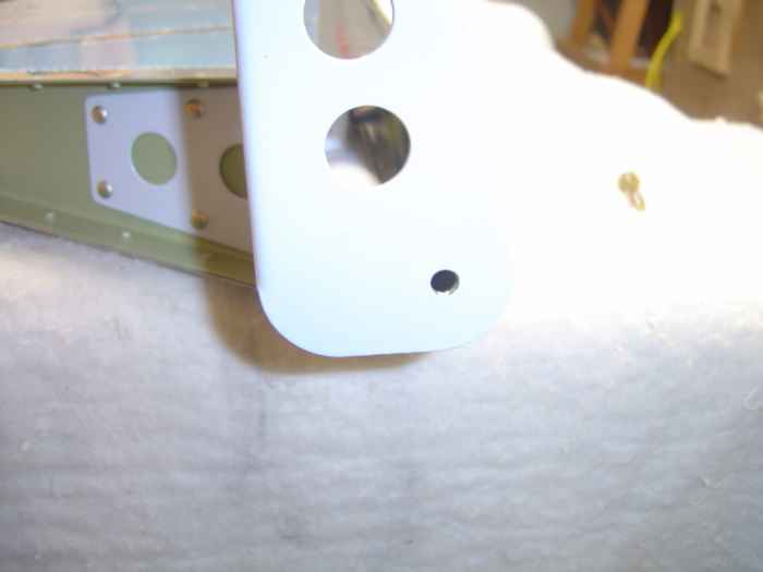 |
The hole then needs to be enlarged to
accommodate the bolt (I believe it was a 1/4" diameter hole). The
bottom hole is what was drilled. |
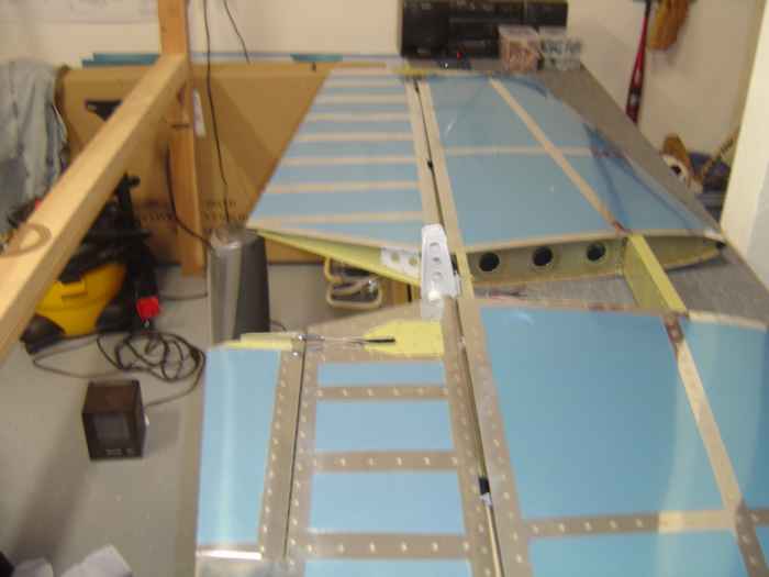 |
Elevator complete! Now on to the
wings. |