![]()
![]()
![]()
![]()
![]()
![]()
![]()
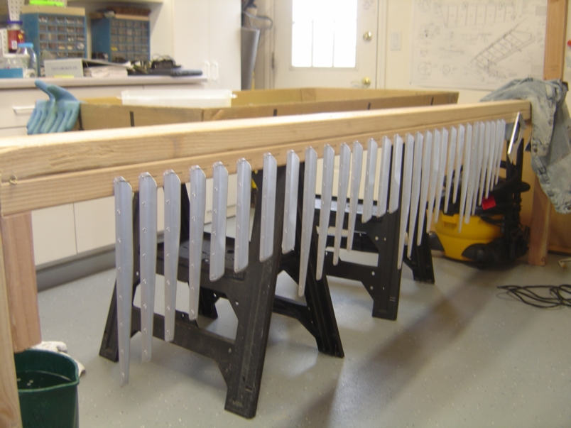 |
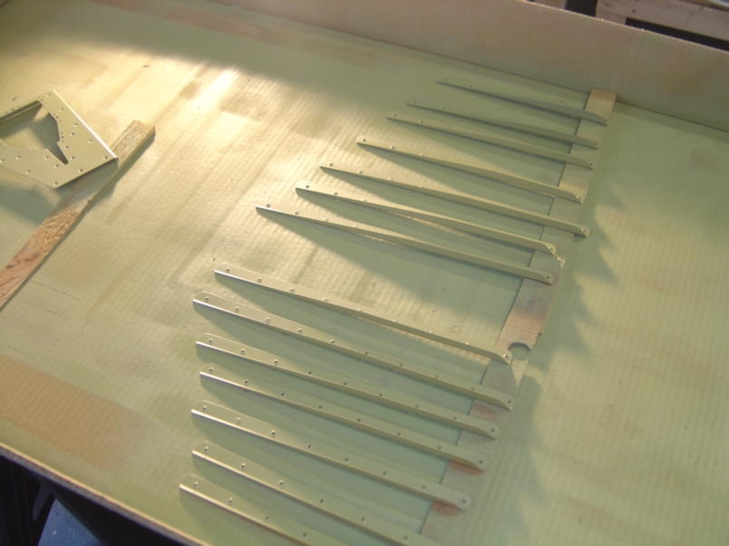
January 3, 2005: (5.5 hrs.) Back to the project after being out of town for the holidays. I began the day by prepping the elevator stiffeners for paint. Here they have been scrubbed in Alumiprep, rinsed and hung to dry. |
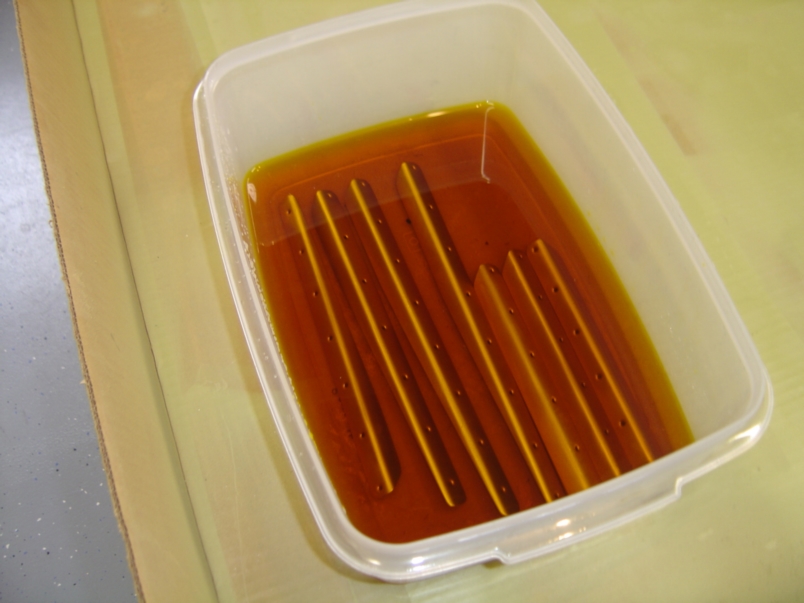 |
Once the stiffeners were dry, I then put batches of them in an Alodine bath for about 2 minutes. |
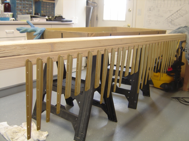 |
After a good rinsing, the stiffeners were once again hung to dry. My wing jig sure is coming in handy for hanging parts :) |
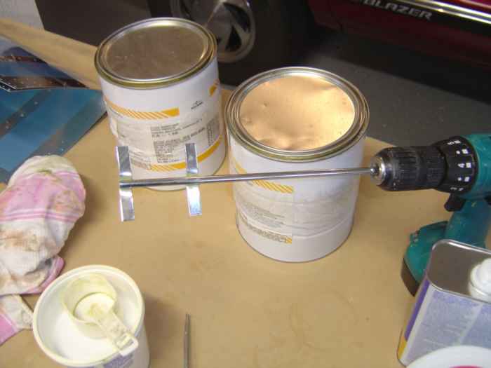 |
While the stiffeners were drying, I got the paint ready. It is important that the catalyst is mixed well prior to adding the hardner. I use a mixer in my cordless drill to for this. |
 |
Here the painted parts are drying under a halogen light. The heat from light makes for a quick drying process. |
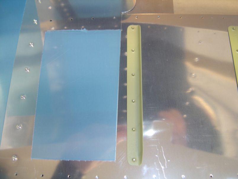 |
After drying for a couple of hours it was time to back rivet the stiffeners to the elevator skins. Here a stiffener has been laid across the rivets. |
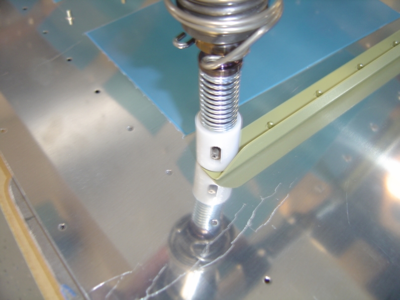 |
This is my rivet gun with back-riveting set. |
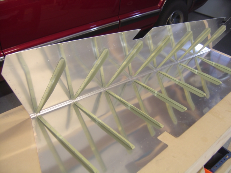 |
All the stiffeners riveted into place. This is the right elevator. I also did the left elevator at the same time. |
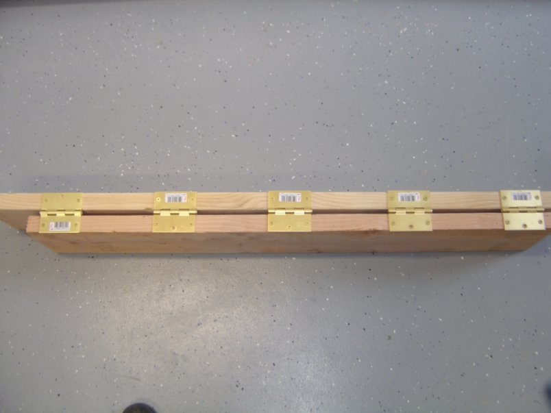 |
The trailing edge of the elevators come pre-bent, but not bent into final position. This is to allow for access for riveting. Once all the stiffeners are riveted into place, the leading edge needs to be bent to its final angle. To do this, I fabricated a bending brake according to the plans. It is a 2'x8' cut into two pieces (44" and 52") held together with five door hinges. |
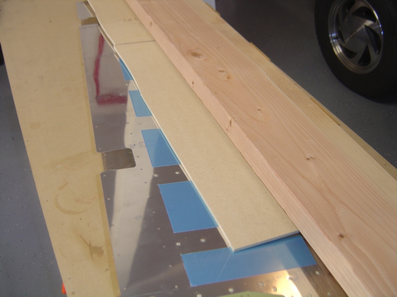 |
It is difficult to tell from this picture, but this is the right elevator in the bending break. To account for the 1/4" gap created by the hinges, I had to place a piece of 1/4" wafer board on one side of the elevator during the bend. The result was a consistent bend and straight trailing edge. |
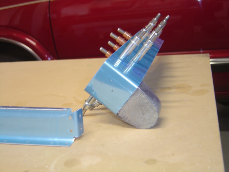 |
Next, I began constructing the skeleton for both the left and right elevators. Both elevators involve basically the same construction with the exception of the trip tab on the left elevator so it made sense to work on them together. Here is a shot of the right outboard ribs, counter-balance weight and skin.. The two forward holes are pilot holes that need to be drilled out to a #12 (all the way through the lead weight). |
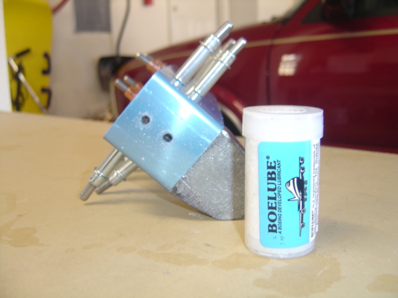 |
It is important to use a lubricant while drilling through the counter-balance weight. Without lubricant, the lead cuttings from the counter weight will plug up your drill bit and potentially damage the counter-balance skin or the weight. I used Boelube with great success. |
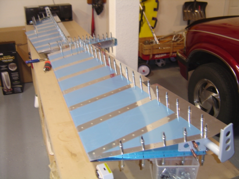 |
Next I attached the skins to the skeletons in preparation for final drilling. In this picture you can see white powder coated control horn cleco'd to the right elevator. |
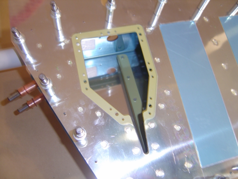 |
This is a picture of the access cover hole for the electric trim tab servo on the left elevator. Inside the hole you can see the stiffener attached to the opposite skin. I have some concerns that this stiffener may interfere with the electric servo. I plan to attach the servo to the access cover and test fit this component before I rivet the left elevator closed. If I detect any interference in the assembly, I will drill out the rivets in the stiffener and then re-attach the stiffener with its flange facing in the opposite direction. |
![]()
![]()
![]()
![]()
![]()
![]()
![]()