 |
March 7 -
9, 2008:
(10.0 hrs.)
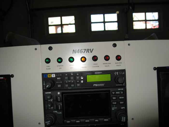
I received the LED annunciators from SteinAir today, so those went
straight into the panel.
|
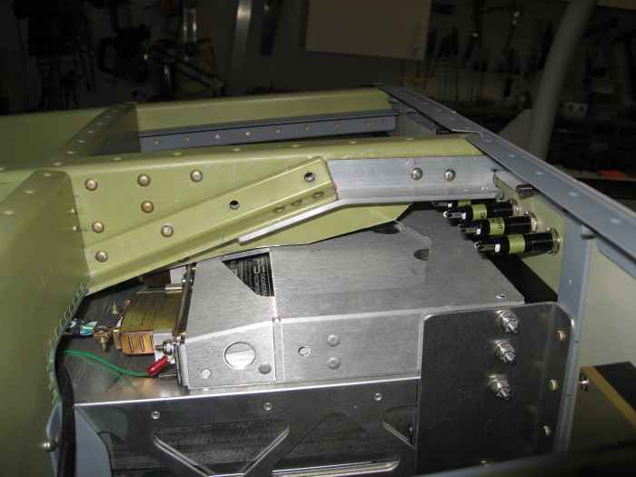 |
I had to trim the center sub-panel rib
slightly more. I then fabricated a stiffener for this rib out of
some angle aluminum and riveted to the rib and existing stiffener.
This entire setup gets bolted to a vertically rising bar that attaches to
the roll-bar. This will be nice and solid.
I also ran some wires to the low voltage warning annunciators and
tested that they worked. |
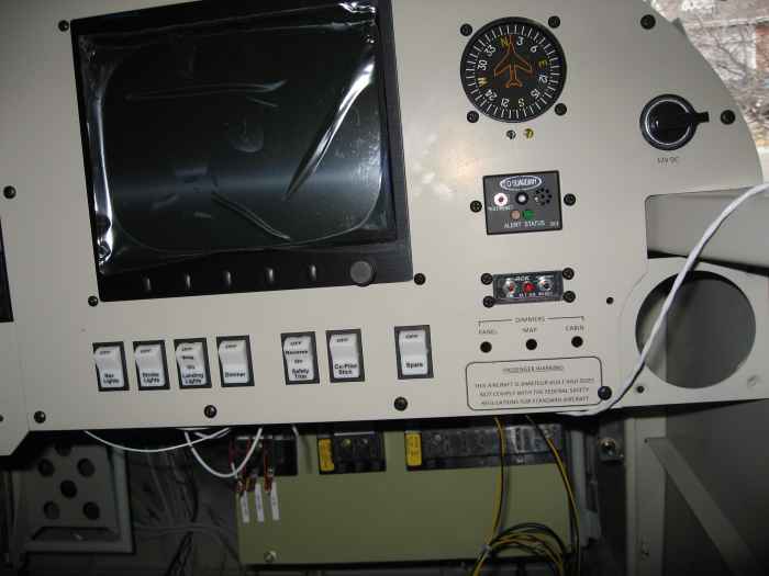 |
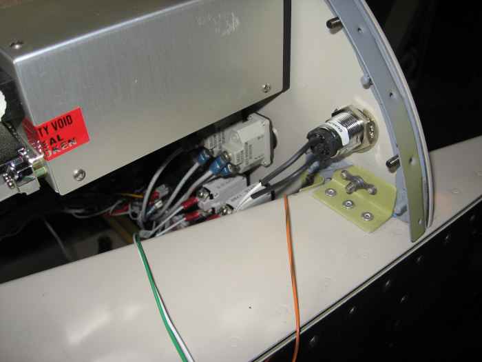
I installed the CO detector and ELT remote
switch into the panel. I went ahead and wired the ELT switch up.
It only required me to crimp on a telephone style plug to the wires.
I will wire the CO monitor later. |
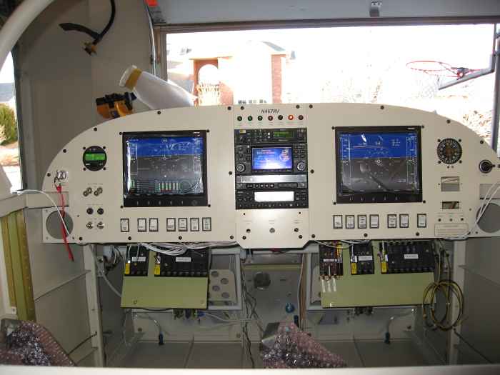 |
A nice shot of the panel all powered up.
No smoke! |
 |
March
14 - April 6, 2008:
(10.0 hrs.)
Did some miscellaneous wiring on the panel. Here I wired up my
starter enable switch. The purpose of this keyed switch is to
enable the starter button on the sticks. This is purely a safety
feature. I don't want someone (or me) accidentally hitting the
start button and swinging the prop.
|
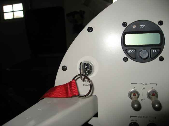 |
Here is a shot of the keyed starter enable
switch. It simply open and closes the start circuit on the starter
relay.
Another thing I did, but did not take a picture of was the wiring for
the CO Detector. It required me to solder a couple wires to a DB9
connector and run them to power and ground. |
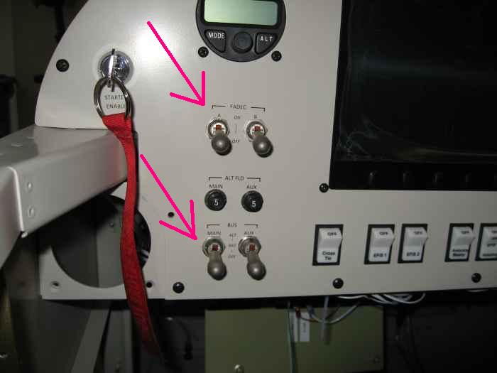 |
I swapped out some switches on the panel.
Specifically, I changed out the top pair of switches from 2-way locking
toggles to 3-way locking toggles. The initial set of switches
powered up the FADEC A and B busses, with the new setup, they both
provide power to the busses, but also 'enable' the FADEC A and B
systems. So they provide OFF-ON-ENABLE functionality. I
still need to change the label on the panel to reflect this 3-way
action. The lower set of toggles are 3-way switches for controlling
the main and auxiliary batteries and alternators. These were
standard toggles that I changed to the locking toggles. I don't
want to accidentally turn the power off to an electrically dependant
airplane. |
 |
April 18 - 20, 2008:
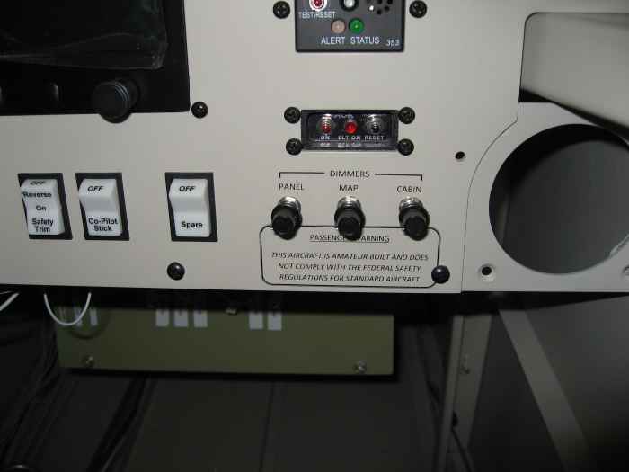
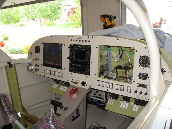
Here are the 3 remote mounted dimmer controls installed in the panel.
Go here for the details... |
 |
c , after spending about 2 weeks trying to trouble shoot why my AFS
3500 would not display the engine data from the FADEC serial bus
controller, I finally determined that my AFS unit had a bad serial port.
Today was a sad day, as I had to pull the co-pilot AFS unit out of
the panel and ship it to AFS for repairs.
|
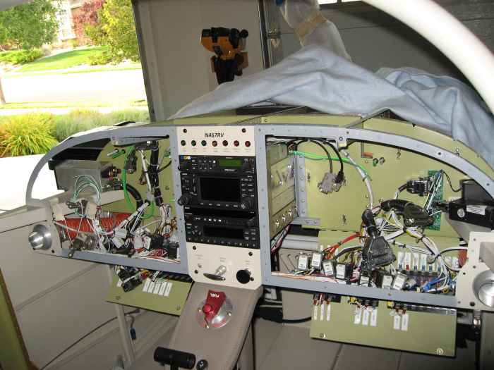 |
Ever since I got my AFS 3500's installed,
I have been wanting to upgrade to the 4500's to get the brighter screen
and faster processor. The unit's will not be available until the
end of the year, but since I had one of the AFS units pulled out of the
panel for repair, it seemed like this might be a good time to prepare
for the upgrade.. The harness is supposed to be plug and play, but
the panel cut out size is different. This means I need to re-cut
the panel opening! Not fun. I do not like taking stuff apart that
I spent a lot of time putting together. Pilot and co-pilot panel
sections are removed. |
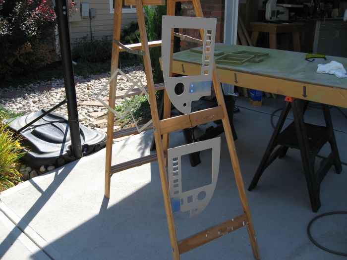 |
I enlarged the opening for the two AFS
units and then re-painted the panels. The portions of the panel
that had been labeled were covered with tape to preserve the lettering.
The new paint seemed to match up well with the old paint.
Here the panels are drying. |
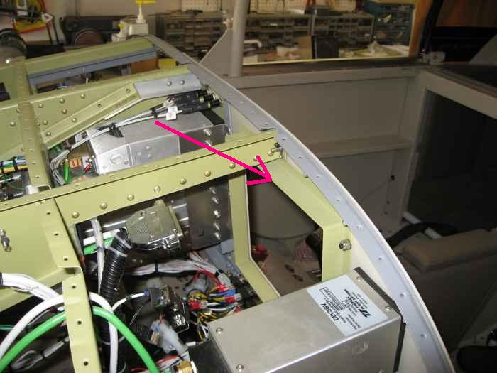 |
Re-installing the panels and all the
equipment. One nice thing about the AFS 4500 units, is that they
use a tray system to mount in the panel. This allows the unit to
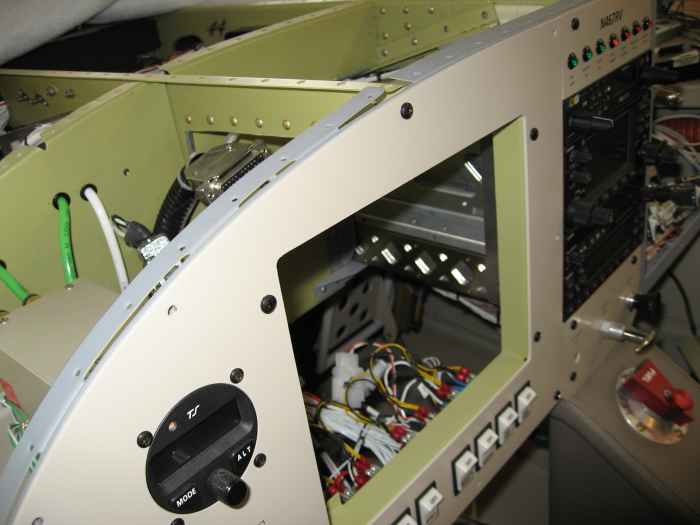
slide in and out from the front. Nice!
Here is the pilot side AFS tray installed. |
 |
Another view of the tray from the front. |
 |
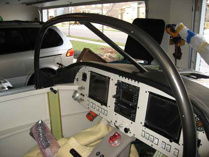
Here is the panel put back together...
almost. Still waiting form my co-pilot AFS 3500 to get back from
repairs.
Probably a little hard to see in this picture, but the co-pilot AFS
3500 fits into the larger 4500 tray system using special 'frame' adapter
from AFS. |
 |
November 1 - 9, 2008:
(8.0 hrs.)
After riveting the top skin on (not pictures)... this was not too
bad. Most of it could be done from the outside by just keeping the
skin peeled back. The fact that my friend Dan came over to help,
made things move rather quickly. The hardest part were the rivets
that required me to lay on my back in the foot-well and buck rivets
along the longerons. Very painful, but doable. I did use
blind rivets where the top skin meets the panel. I had too much
stuff in there to work around with a bucking bar. Plus, these
rivets will never be seen since I will be covering the glare shield...
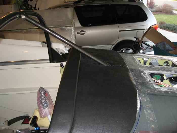
Speaking of which, here is my glare shield all upholstered. I
bought the padded edge pre-made from Classic Aero and then ordered some
extra material to upholster the the rest of the glare shield to match.
I think it turned out pretty nice!
|
 |
Here is another shot.
One other thing to point out is that I pained the roll-bar black to
match the paint I used on the inside of the canopy. |
|
|
|


