 |
September 15, 2004: Empennage kit arrives! I
am out of town :(
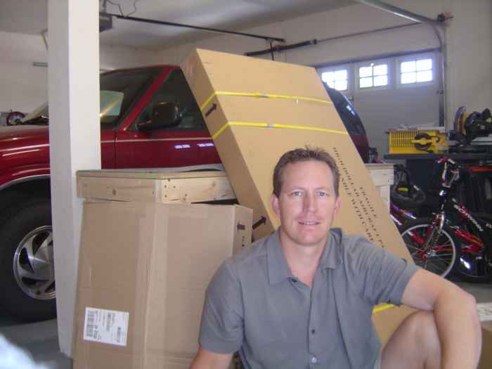
September 17, 2004: This is me with my empennage
kit in the workshop. I spent about 1.5 hours sorting through the kit and
taking inventory. I was not missing any pieces. Things were packed
pretty nicely. My only complaint is that Van's used duct tape to hold down
the skins and it was a pain to remove without also removing the blue plastic
protective layer which I want to keep intact as long as I can to protect the Alclad coating.
|
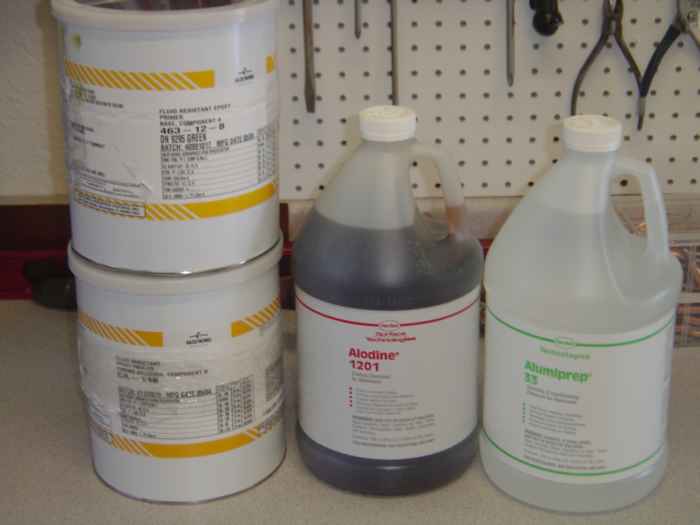 |
I also received my hazardous materials order from Aircraft
Spruce. This is the Alumiprep, Alodine, and Epoxy Primer |
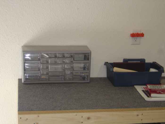 |
I picked up this organizer from Home Depot and use it to
store all the small parts that came with the empennage kit (rivets, bolts, nuts,
misc. hardware). |
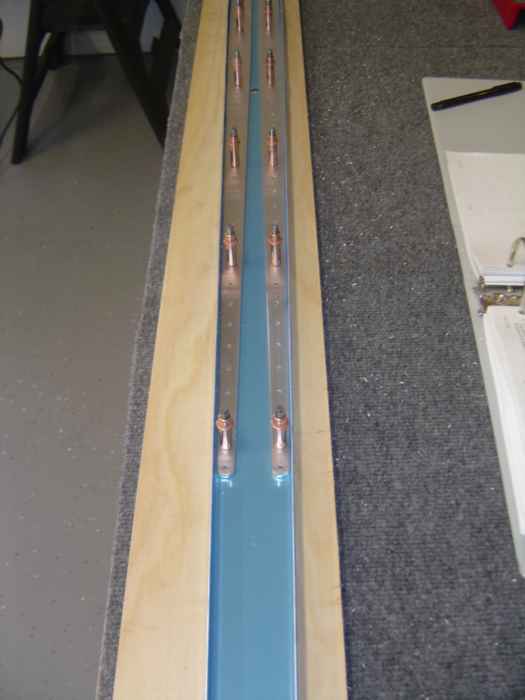 |
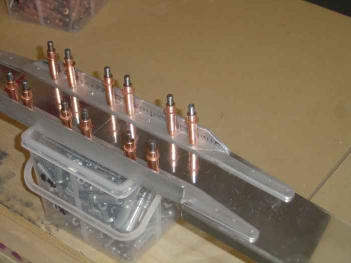
September 18, 2004: (3 hrs.) Began assembly of the
rear Horizontal Spar. The stiffeners needed there inside and outside edges
rounded and smoothed. Also, the ends of the stiffeners need a 1/4" radius.
I did all this rounding and smoothing on my disc sander. I also cleco'd
and drill matched the stiffeners to the rear HS, then I removed the parts and
deburred everything
|
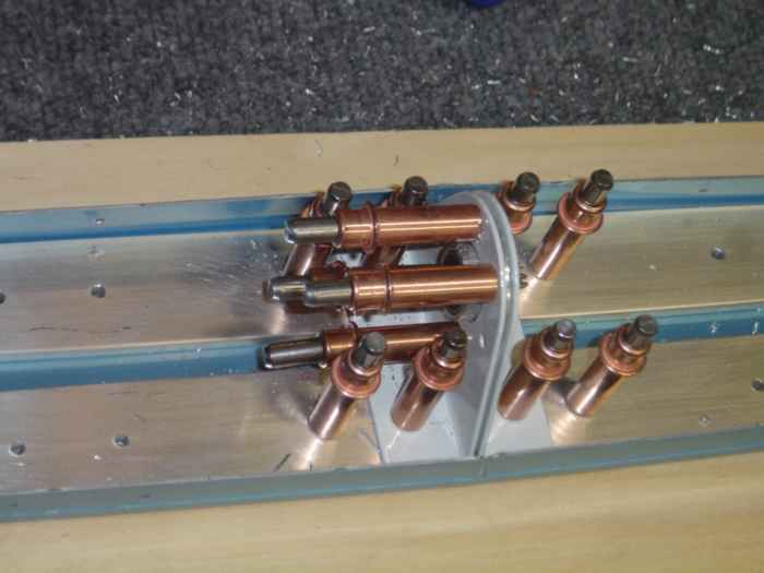 |
Next, I mounted all the hinge brackets to the rear HS and
matched drilled the parts. Here you can see the center bearing assembly
that has been cleco'd and matched drilled. I un-assembled everything and
deburred all the holes
|
 |
September 19, 2004: (3 hrs.) Today I
assembled the forward HS. This involved first trimming the upper and lower
angle stiffeners so that they were tapered towards the ends down to a 1/4"
radius at the tips. I used the bandsaw to trim off the majority of
material, then I switched to the disc sander to smooth and round the edges.
With this completed, I then put in a 6 degree bend on the tapered ends of the
stiffeners per the drawings. This was actually quite easy, I just held the
part in a vise between two blocks and bent it by hand. I then used a
protractor to verify that I indeed had 6 degrees of bend. Next, I notched
the forward HS to make room for the bend they are to receive. I used my
Wiss tin snips to do this job... Next time I would use my bandsaw. The tin
snips do not leave a clean straight cut line when you are cutting into the bend
radius of the spar flange. Once the flanges were cut and cleaned up, I put
6 degrees of bend in the inward ends of the forward HS using blocks clamped to
the spar. Here you see the cleco'd and drill matched forward HS
assembly. |
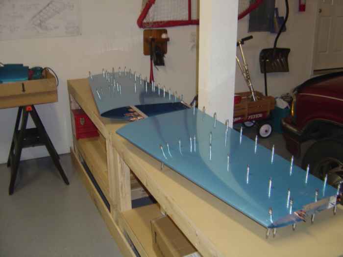 |
Here I have cleco'd the spars together with the HS706,
HS707, and HS708 ribs. The HS404 and HS405 ribs have been left out at this
point. Those will be slid into position, clamped, and matched drilled to
the skins, as well as, to the the front and rear spars. |